Filtering structure for swimming pool

Inactive Publication Date: 2007-08-16
PISCINES WATERAIR & PROCOPI
View PDF18 Cites 3 Cited by
  • Summary
  • Abstract
  • Description
  • Claims
  • Application Information

AI Technical Summary

Benefits of technology

[0016] The disposition in this manner puts a complete end to load losses as a result of pipes such as those in the prior art and allows the utilization of more economical and less energy-consuming pumping means.
[0031] In this manner the user may, at his / her convenience modify the water flow in the pool and make the most of the shape of the swimming pool in order to avoid stagnation zones where the water would not be correctly turned over.

Problems solved by technology

The presence of these pipes, even if less important when the filtering and pumping device is in the form of a casing, inevitably brings about load losses diminishing the performance of the known systems.
Moreover, in the prior art devices, the connecting pipes often pass above the water level, resulting in priming difficulties.
The use of oversized pumping means results of necessity in increased production costs, but also in higher energy consumption and therefore a higher electricity bill of the owner of a pool equipped with such devices.
Furthermore, the devices whose pumping and electric control means are arranged in an underground location adjacent to or remote from the immersed portion, are subjected to flooding in case of heavy rains, resulting inevitably in serious damage to the pumping system or imposing considerable and costly work in order to carry out gravitational drainage at the bottom of the technical location.

Method used


Image

  • Filtering structure for swimming pool
  • Filtering structure for swimming pool
  • Filtering structure for swimming pool

Examples


Embodiment Construction

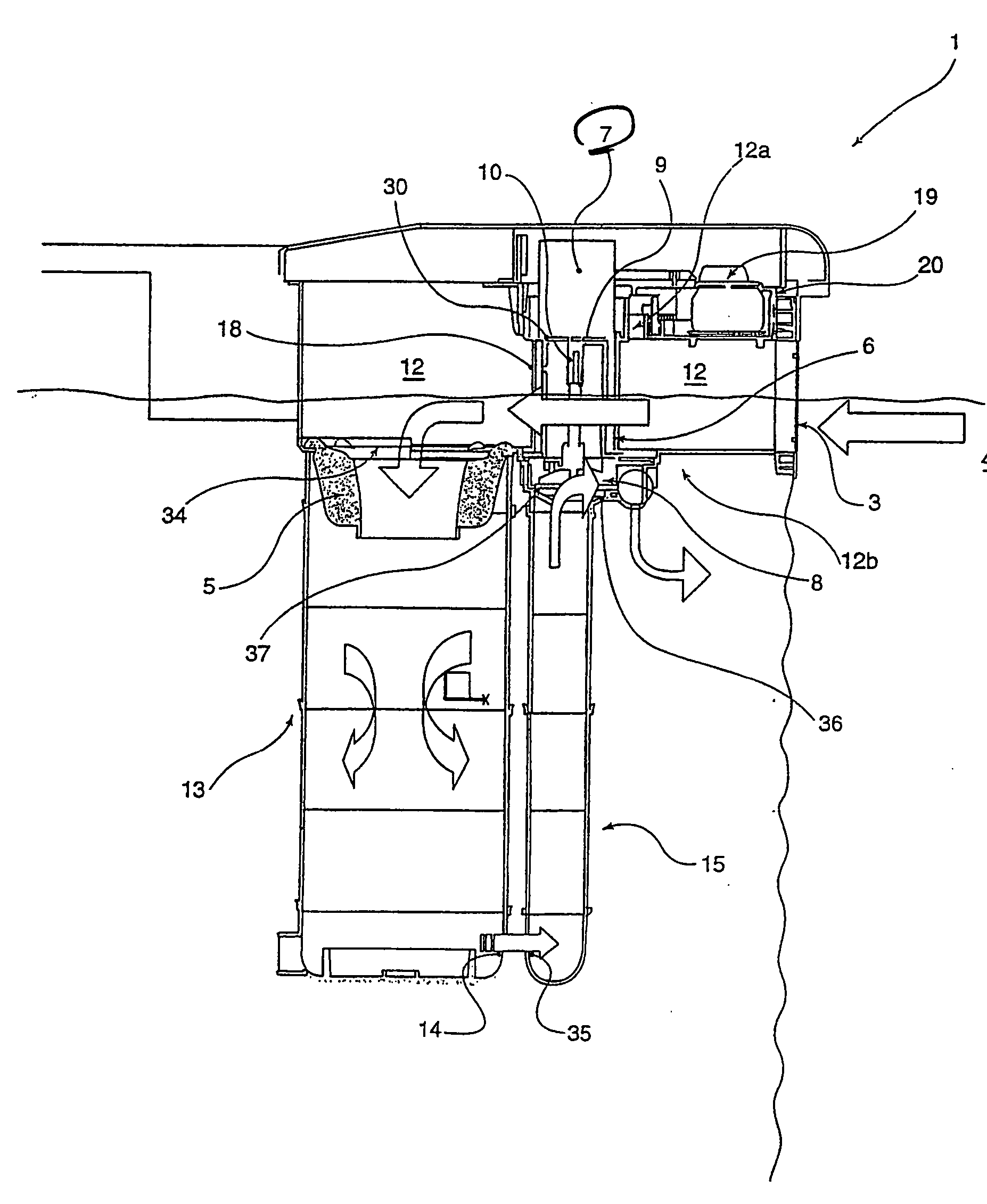
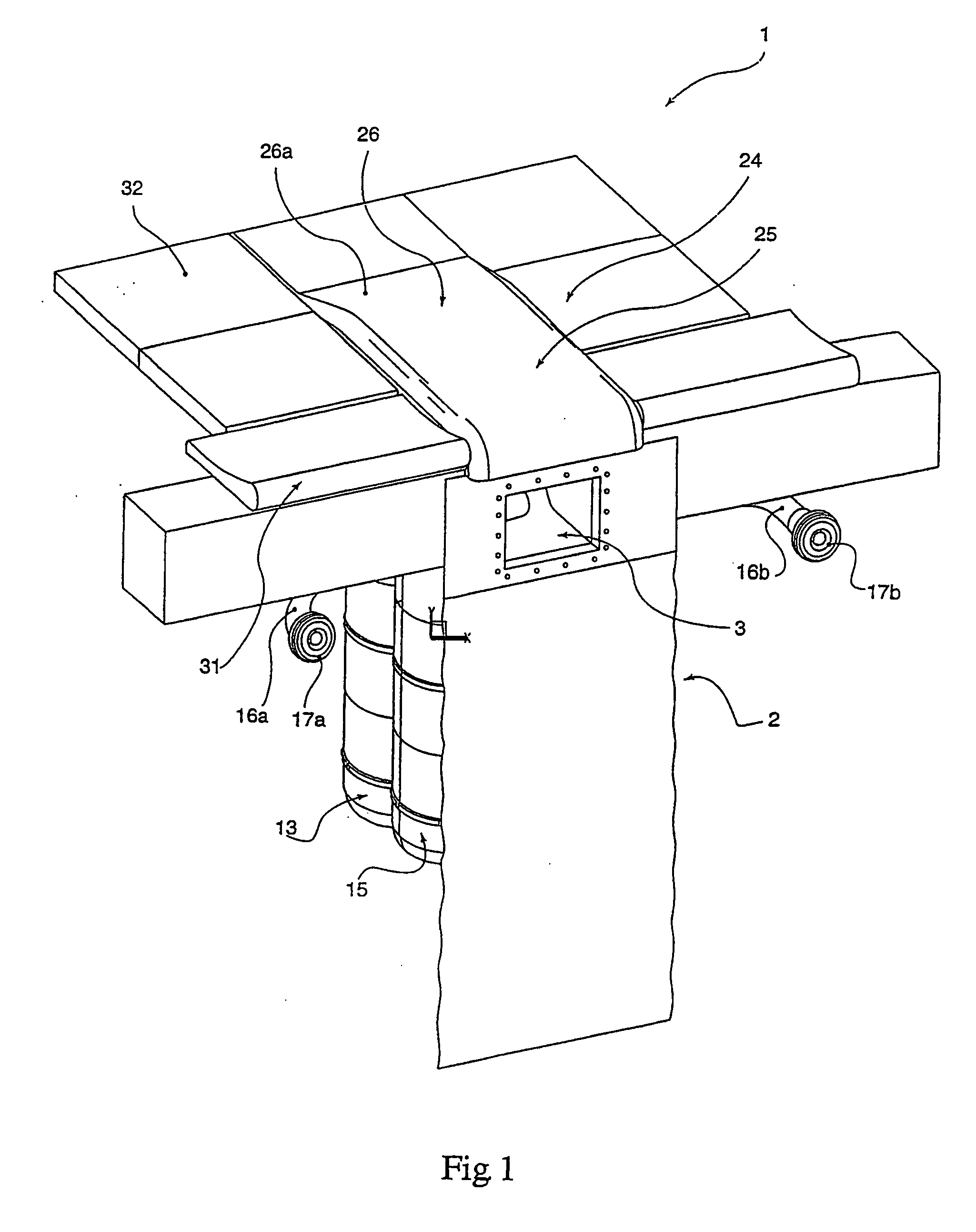
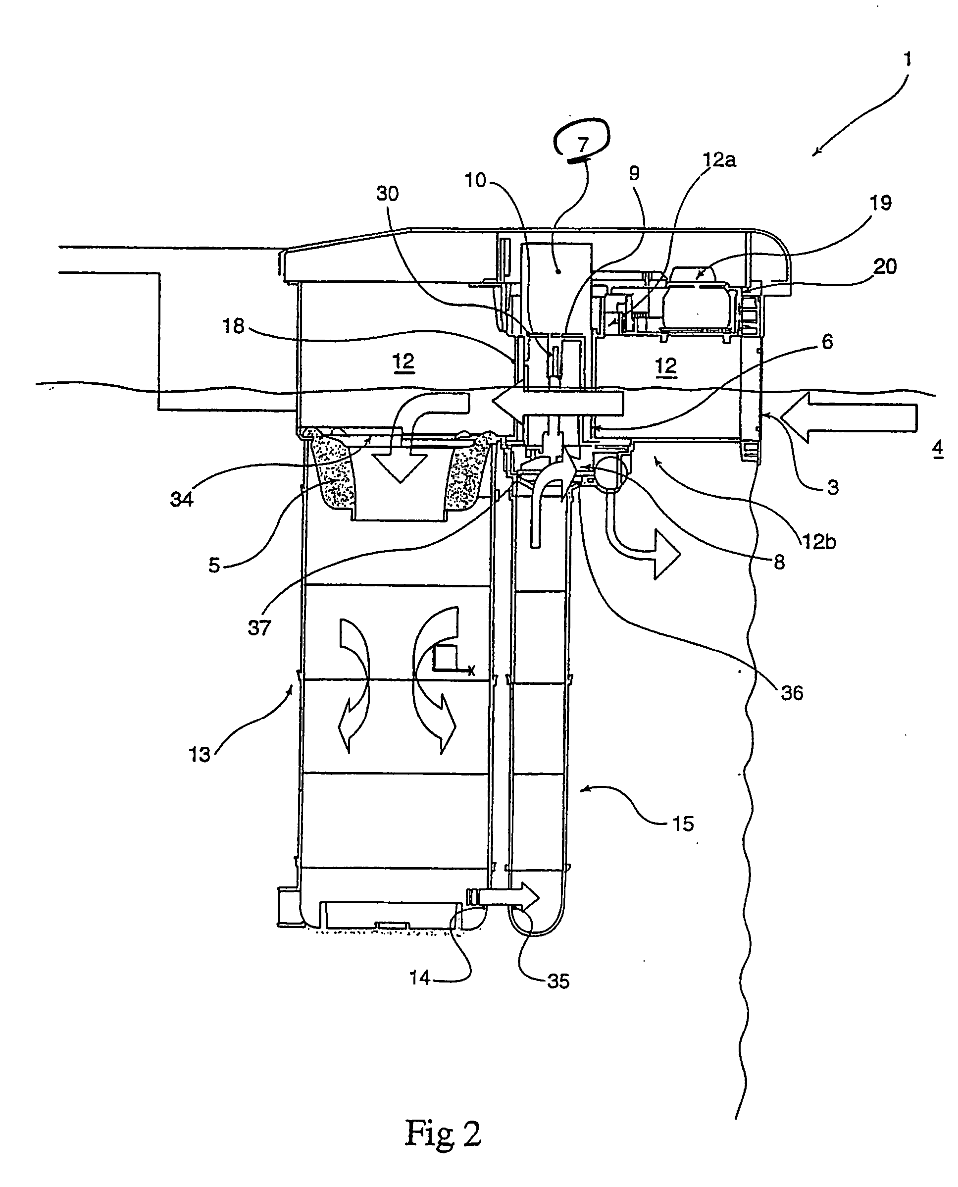
[0039] The filtering structure (1) according to the invention is incorporated in the generally vertical wall (2) of a swimming pool and comprises a suction port (3) partly immersed in the water (4) of the pool basin, the level of which is shown in FIG. 2 by an uneven line. Referring to this figure, the filtering structure (1) according to the invention also comprises filtering means and pumping means (6). The pumping means (6) are composed of an electric motor (7) associated with a hydraulic part (8) composed of a flange (36) in which a turbine (37) is accommodated and intended for immersion in the water in the course of a filtering cycle to move it. The electric motor (7) drives the hydraulic part (8) by means of a transmission shaft (9) on which the turbine (37) is fixed. In the embodiment shown in particular in FIG. 2, the motor (7) is in a vertical position and its output shaft (10) is coupled to the transmission shaft (9).

[0040] The suction port (3) opens towards a generally h...


PUM

PropertyMeasurementUnit
Volumeaaaaaaaaaa

Abstract

A filtering structure intended to be incorporated in a vertical swimming pool wall has a filtering device and a pumping device with the pumping device having an electrical part, including an electric motor, and a hydraulic part equipped with a turbine. The filtering structure has a suction port facing towards a nominally horizontal access passageway partly submerged in water, and emerging towards a nominally vertical tank arranged thereunder. The filtering structure has a tank communicating with a nominally vertical column, partly in the upper part of which is arranged the hydraulic part. The electrical part is arranged above the level of the water to be treated and is contained in the nominally horizontal access passageway, while the hydraulic part is immersed in a volume of filtered water.

Description

CROSS REFERENCE TO RELATED PATENT APPLICATIONS [0001] The present application is a continuation of U.S. patent application Ser. No. 10 / 491,177 filed Aug. 13, 2004 entitled “Filtering Structure For Swimming Pool,” now pending, which claims priority of PCT International Application No. PCT / FR02 / 03333 filed on Sep. 30, 2002, and French Application No. 01 / 12635 filed on Oct. 1, 2001. The aforementioned applications are hereby incorporated herein by reference in their entirety.BACKGROUND OF THE INVENTION [0002] 1. Field of the Invention [0003] The present invention concerns the field of swimming pool water filtration and, more particularly, relates to a filtering structure designed to be incorporated in one of the generally vertical walls of a swimming pool. [0004] 2. Description of Related Art [0005] A plurality of filtering devices of this type have to date been proposed. They comprise mainly a portion immersed in the water of the swimming pool, equipped with a suction port and a disch...

Claims


Application Information

Patent Timeline
IPC IPC(8): C02F1/00B01D35/027E04H4/12
CPCB01D35/027B01D35/0276E04H4/1218B01D35/26E04H4/1272
Inventor BRAUN, JACQUESBAYSSE, PIERRELE GUILLOU, PIERRE
Owner PISCINES WATERAIR & PROCOPI
Why Eureka
Try Eureka