Image display device and image display system

a technology which is applied in the field of image display device and image display system, can solve the problems of reducing the sense of reality, the user cannot appreciate images while paying attention to outside information, and the face collision risk should be evaded, so as to achieve high image quality and high field angle, and the effect of providing safe and reliable service to users

Inactive Publication Date: 2007-08-16
NISHI KENJI
View PDF10 Cites 37 Cited by
  • Summary
  • Abstract
  • Description
  • Claims
  • Application Information

AI Technical Summary

Benefits of technology

[0086] In accordance with the present invention, there can be provided an image display device through which images with high image quality and high field angle are, in a space-saving manner, safely provided to the user, and, at the time, with the personal image display devices' disadvantages being saved, even multiple persons can enjoy the images.

Problems solved by technology

However, in the above-described case where the heavy object is supported by an outside member, since there is the possibility that the heavy object is driven in the vicinity of the face, it is required that it properly follow the face portion and that the risk that the face collides with the heavy object should be evaded.
Further, also in the case of displays for personal use, when the system is structured such that the entire field of vision is light-shielded, there is the disadvantage that the user cannot appreciate images while paying attention to outside information.
While to avoid this disadvantage, with respect to eyeglass type displays and head mount type displays, ingenuities in which, for example, see-through portions through which the peripheral portions can be observed or windows, located at the periphery of the eyeglass, for observing the outside are disposed are made, the ingenuities themselves decrease the sense of reality, and thus there is the disadvantage that the original sense of reality associated with a large screen image cannot be obtained.
Still further, with respect to eyeglass type displays and head mount type displays, there is the disadvantage that while they can be utilized for personal use, multiple persons cannot enjoyably appreciate images.

Method used


Image

  • Image display device and image display system
  • Image display device and image display system
  • Image display device and image display system

Examples


first embodiment

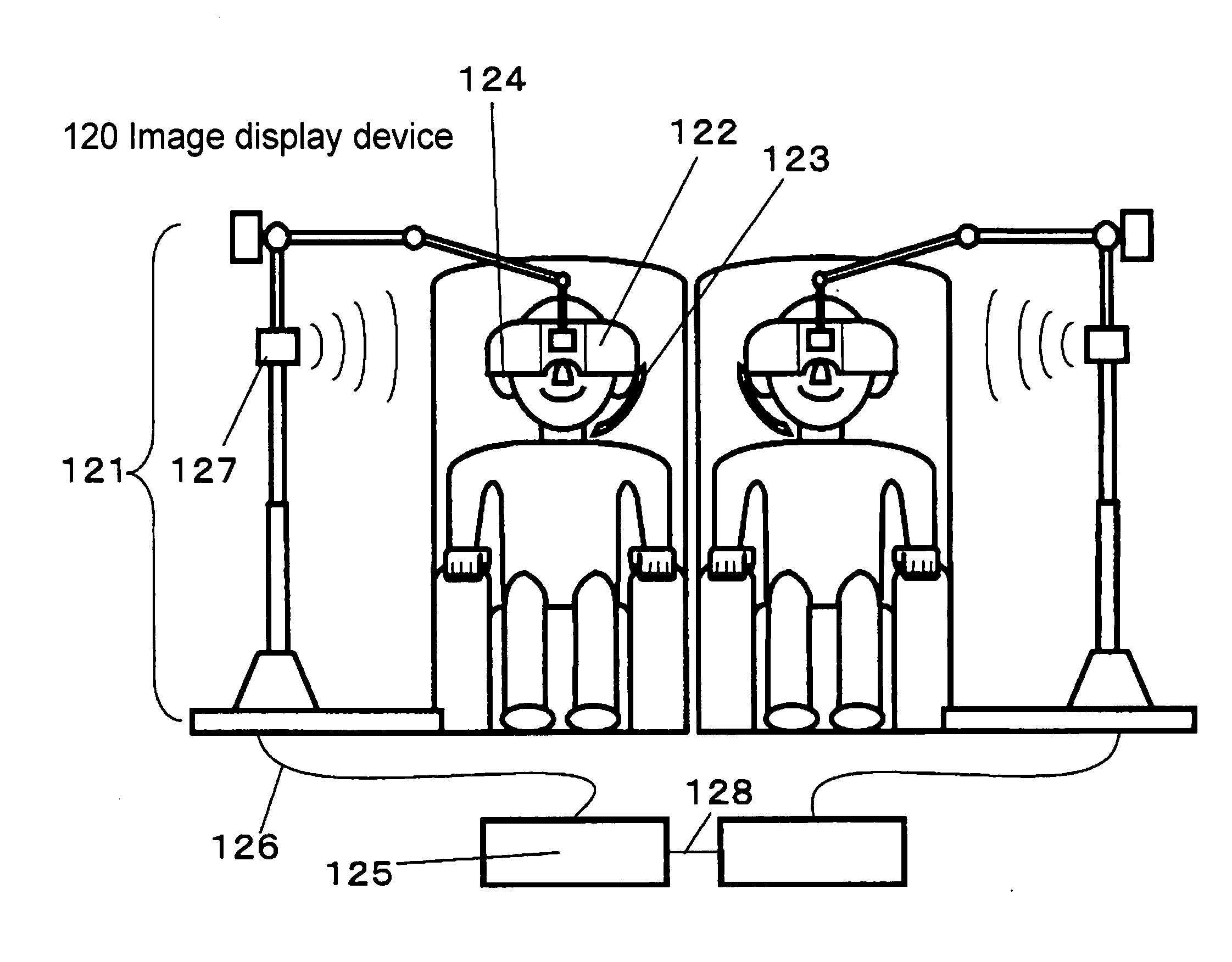
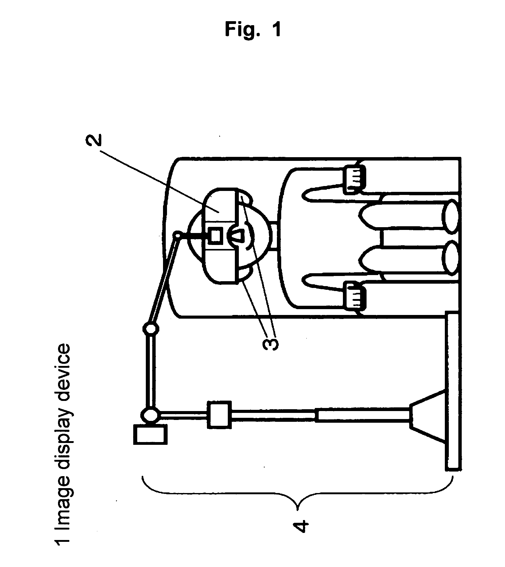
[0133] As shown in FIG. 1, image display device 1 of a first embodiment is provided with image display portion 2, sound output portions 3, and supporting portion 4. Image display portion 2 projects, via eyepiece optical systems which respectively correspond to each of the both eyes of a user (which will be detailed later), a light emitted from a two-dimensionally light emitting type photoelectric device, not shown, which is perpendicular to the light beam emitting direction onto the eyeballs of the user. Further, sound output portions 3 are disposed by elastic members, which will be described later, so as to sandwich the both ears of the user to output sound. Further, as shown in FIG. 1, supporting portion 4 supports image display portion 2 at its portion that is not in contact with the user.

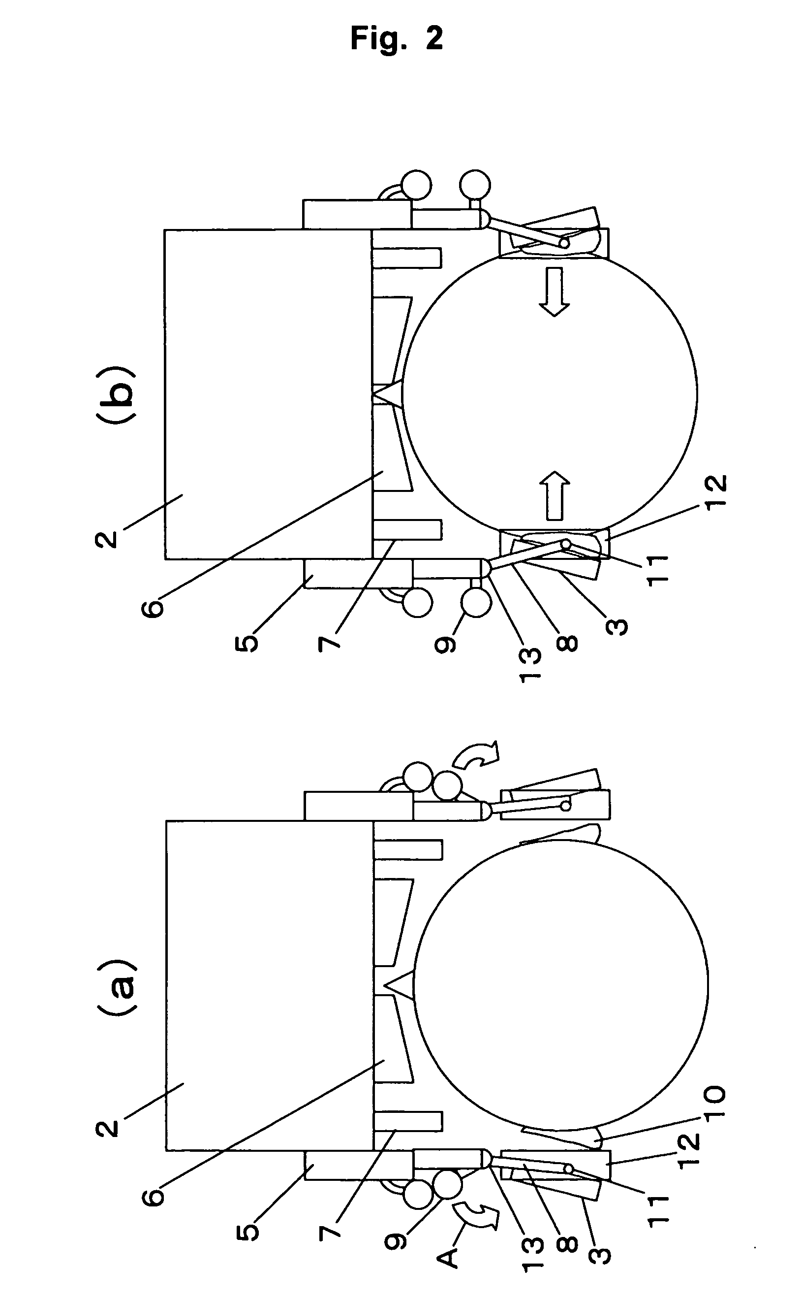
[0134] First, a face sandwiching mechanism supported by image display portion 2 will be described. As shown in FIGS. 2(a) and 2(b), image display portion 2 supports face sandwiching portions 5....

second embodiment

[0191] As shown in FIG. 23, image display system 50 of a second embodiment is provided with voice input portion 51, image display portion 52, sound output portions 53, supporting portion 54, and, further, chair portion 55. Voice input portion 51 can, with it being moved in the direction of arrow F, perform on / off of voice input. Further, image display portion 52 projects, via eyepiece optical systems which respectively correspond to each of the both eyes of a user, a light emitted from a two-dimensionally light emitting type photoelectric device, not shown, which is perpendicular to the light beam emitting direction onto the eyeballs of the user. Further, sound output portions 53 output sound to the user. Further, as shown in FIG. 23, supporting portion 54 supports image display portion 52 at its portion that is not in contact with the user.

[0192] First, supporting portion 54, which supports image display portion 52, will be described. FIG. 24(c) is a cross-section drawing of suppo...

third embodiment

[0219] Image display device 100 of a third embodiment has a configuration almost similar to that of FIG. 23 of the second embodiment. Thus, with illustration and configuration description thereof being omitted, description will be made hereinafter by using symbols similar to those in FIG. 23.

[0220] In the following, characterizing portions of the third embodiment will be described.

[0221]FIG. 29 is a cross-section drawing of supporting portion 54 of image display device 100. As shown in FIG. 29, supporting portion 54 has hardwiring 101 along a string-like flexible member 102 in supporting portion 54. And, hardwiring 101 is led from image display portion 52 to weight 58 via pulleys for wiring 103, 104, and 107. Hardwiring 101 is fixed, at its intermediate portion, to wiring fixing portion 105 attached to weight 58. Hardwiring 101 is slackened so that it has a sufficient margin for the up and down drive of weight 58 (see region I in FIG. 29) and then is connected to the outside (e.g....


PUM


Abstract

An image display device comprising a display portion that projects, via eyepiece optical systems which respectively correspond to each of the both eyes of a user, a light emitted from a two-dimensionally light emitting type photoelectric device which is perpendicular to the light beam emitting direction onto the eyeballs of said user, a supporting portion that supports the display portion at its portion that is not in contact with the user, and a face contact portion that is supported by the display portion and is capable of changing the distance between the eyepiece optical systems and the eyes of the user, whereby images with high image quality and high field angle are, in a space-saving manner, safely provided to the user, and, at the time, with the personal image display devices' disadvantages being saved, even multiple persons can enjoy the images.

Description

TECHNICAL FIELD [0001] The present invention relates to an image display device that is used with it being positioned near to the eyeballs and relates to an image display system. Background Art [0002] Generally, image display devices can be divided into devices for multiple persons to enjoy images displayed thereon such as televisions and projectors, and personal display devices by which displayed images are enjoyed personally such as personal computers, televisions set in the chairs in an airplane, and cell phones. In the case of the former ones, for multiple persons to appreciate images, the images are required to be displayed at a position distant from the picture plane, and thus there is the disadvantage that there arises a restriction with respect to the size of the display, and, at the time, a large space is required. On the other hand, since the latter ones are for personal use, images may be displayed near the picture plane, and even if the picture plane itself is small, the...

Claims


Application Information

Patent Timeline
Patent Type & Authority Applications(United States)
IPC IPC(8): G09G5/00G02B7/00G02B25/00G02B27/00G02B27/01G02B27/02H04N5/64H04N5/74
CPCF16M11/10H04N5/7491F16M11/2057F16M11/2064F16M11/24F16M13/04F16M2200/047G02B7/001G02B25/001G02B27/0172G02B27/0176G02B27/027G02B2027/0132G02B2027/0136G02B2027/0178F16M11/2014
Inventor NISHI, KENJI
Owner NISHI KENJI
Why Eureka
Try Eureka