
GFCI that cannot be reset until wired correctly on line side and power is applied

a fault circuit interrupter and line side technology, applied in the direction of earth fault current operating/releasing mechanism of protective switches, fault current resposes, etc., can solve the problems of power interrupt, permanent lockout, power interrupt, etc., and achieve the effect of preventing the miswiring of a protection devi

Inactive Publication Date: 2007-08-16
HUBBELL INC
View PDF48 Cites 11 Cited by
  • Summary
  • Abstract
  • Description
  • Claims
  • Application Information

AI Technical Summary

Benefits of technology

[0012] According to an embodiment of the present invention, an apparatus and method for preventing the miswiring of a protection device is employed. The protection device includes line terminals and load terminals. The protection device further includes a latching mechanism, adapted to move between a closed state which establishes electrical contact between said line and load terminals, and an open state which prevents electrical contact between said line and load terminals; and an initial reset prevention mechanism, adapted to prevent said latching mechanism from being set in said closed state until power is applied to said line terminals.

Problems solved by technology

Generally, the ground fault condition results when a person comes into contact with the line side of the AC load and an earth ground at the same time, which is a situation that can result in serious injury.
However, having a permanent lockout, which prevents the GFCI from operating, can be undesirable.
For example, if a homeowner is entertaining guests in the kitchen, a power interrupt can occur requiring the GFCIs to be reset.
In front of guests, this can prove to be embarrassing and inconvenient to the homeowner.
When a ground fault occurs in the protected circuit, or when the test button is depressed, the GFCI device trips and an internal circuit breaker opens both sides of the AC line.
However, the GFCI disclosed in the Bienwald et al. patent does not provide an indication of a defective solenoid.
However, if the GFCI is miswired, this poses a problem.
However, the installer would be unaware that the GFCI is not providing ground fault protection even when a fault condition is detected.

Method used


Image

  • GFCI that cannot be reset until wired correctly on line side and power is applied
  • GFCI that cannot be reset until wired correctly on line side and power is applied
  • GFCI that cannot be reset until wired correctly on line side and power is applied

Examples


Embodiment Construction

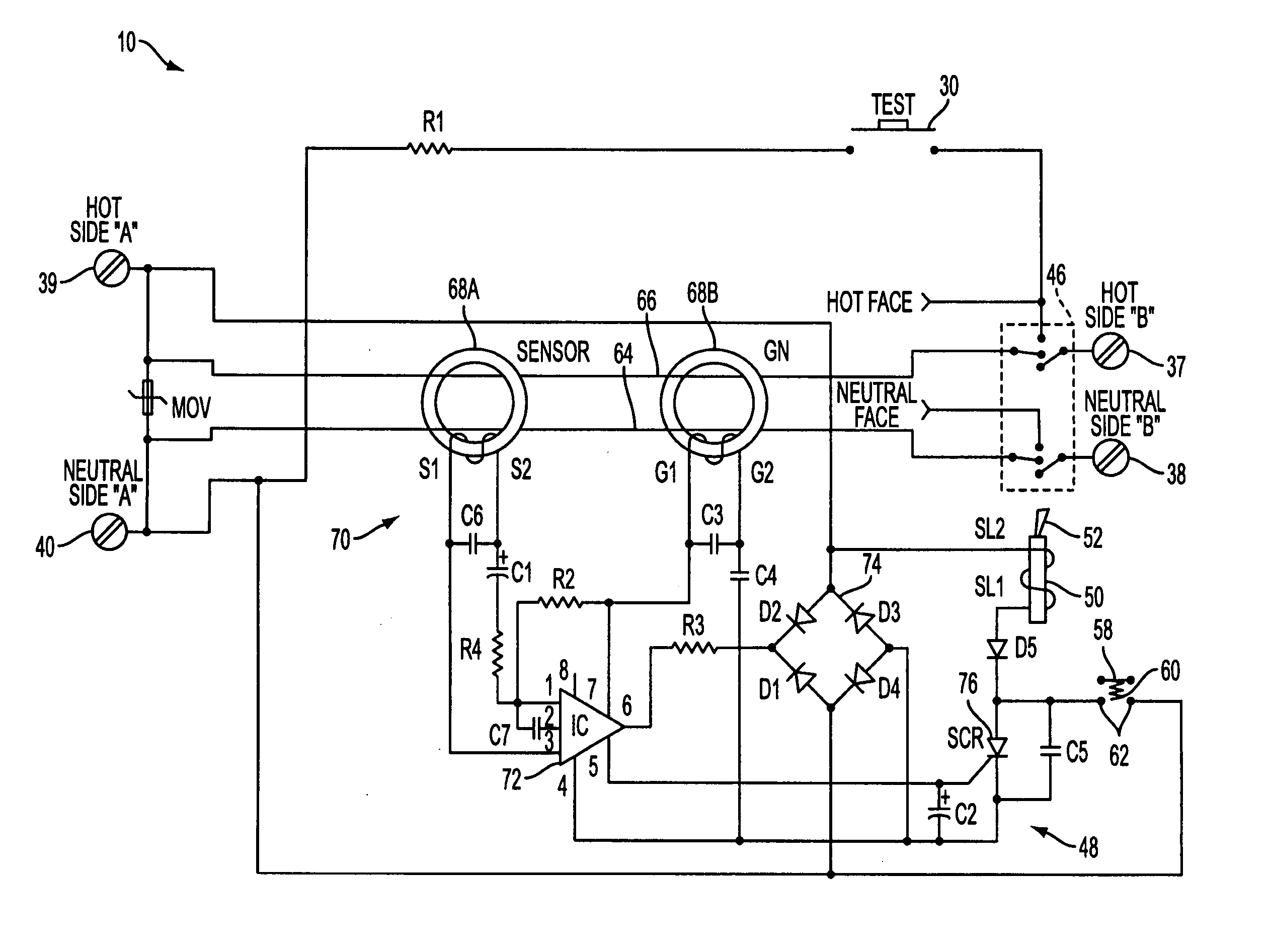
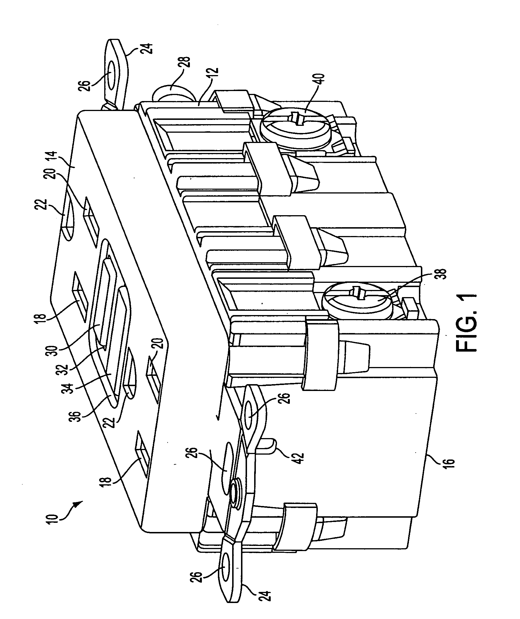
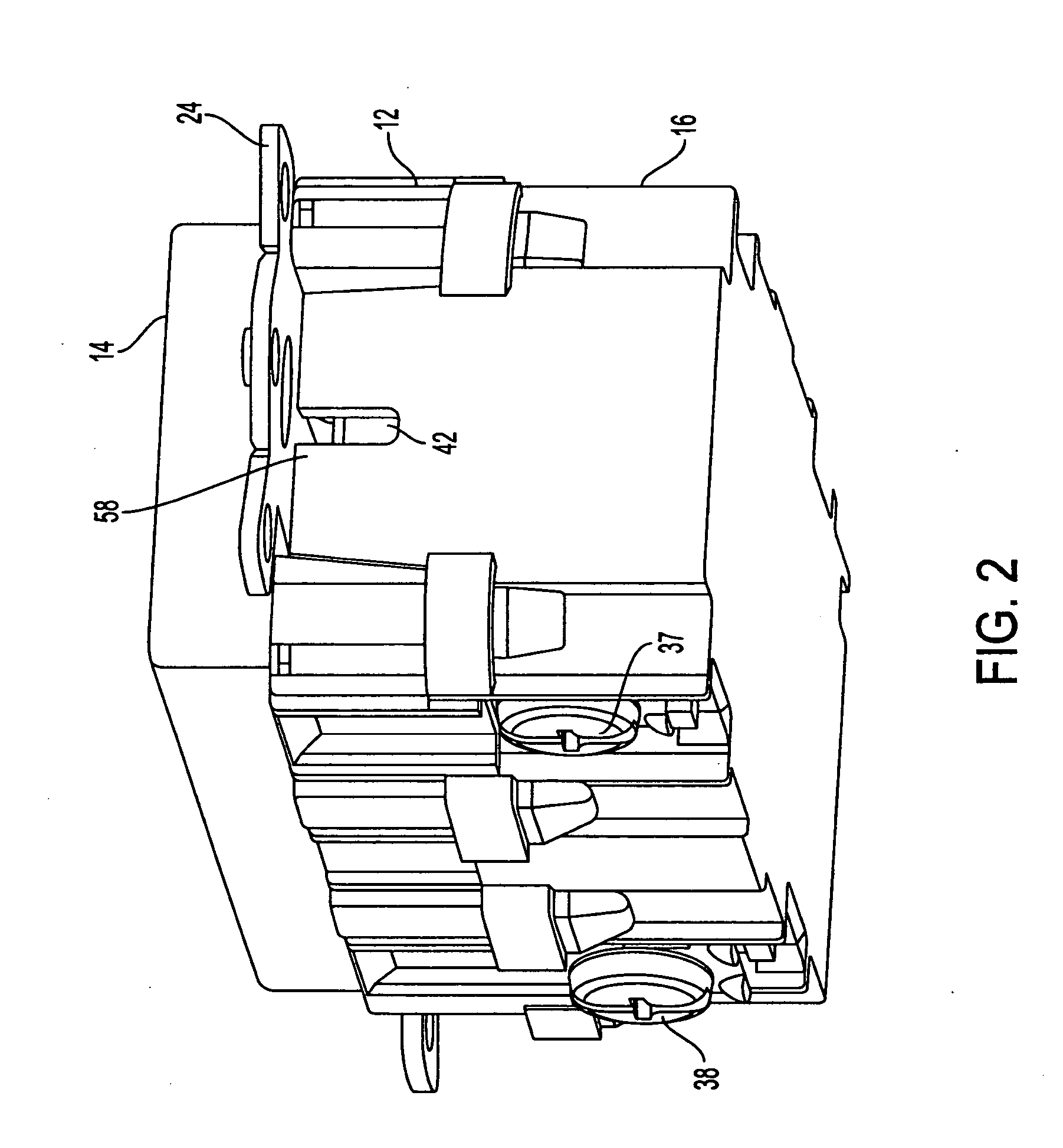
[0025]FIG. 1 is a perspective view of an example of a ground fault circuit interrupting (GFCI) device 10 in accordance with an embodiment of the present invention. The GFCI device 10 comprises a housing 12 having a cover portion 14 and a rear portion 16. The GFCI also includes an inner housing 13 (See FIG. 5) when the cover portion 14 is removed from the rear portion 16. The cover portion 14 and rear portion are removably secured to each other via fastening means such as clips, screws, brackets, tabs and the like. The cover portion includes plugin slots (also known as face receptacles) 18 and 20 and grounding slots 22. It will be appreciated by those skilled in the art that plugin slots 18 and 20 and grounding slots 22 can accommodate polarized, non-polarized, grounded or non-grounded blades of a male plug. The male plug can be a two wire or three wire plug without departing from the scope of the present invention. The GFCI receptacle 10 further includes mounting strap 24 having mou...


PUM


Abstract

An apparatus and method for preventing the miswiring of a protection device. The protection device includes line terminals and load terminals. The protection device further includes a latching mechanism, adapted to move between a closed state which establishes electrical contact between said line and load terminals, and an open state which prevents electrical contact between said line and load terminals; and an initial reset prevention mechanism, adapted to prevent said latching mechanism from being set in said closed state until power is applied to said line terminals.

Description

PRIORITY CLAIM [0001] This application is a continuation of application Ser. No. 10 / 434,101 filed May 9, 2003 which claims benefit from U.S. Patent Application Ser. No. 60 / 378,647, filed on May 9, 2002 entitled “GFCI With Reversible Line / Load Wiring Capability”, the entire contents of which is incorporated herein by reference. CROSS REFERENCE TO RELATED APPLICATIONS [0002] Related subject matter is disclosed in U.S. patent application Ser. No. 10 / 032,064, filed on Dec. 31, 2001 entitled “Ground Fault Circuit Interrupter (GFCI) With A Secondary Switch Contact Protection”, the entire contents of which is incorporated herein by reference.FIELD OF THE INVENTION [0003] The present invention generally relates to ground fault circuit interrupter (GFCI) devices. More particularly, the invention relates to a GFCI device that isolates the face terminals from the load side and prevents an initial miswiring of the GFCI from the load side. BACKGROUND OF THE INVENTION [0004] GFCI devices are desi...

Claims


Application Information

Patent Timeline
Patent Type & Authority Applications(United States)
IPC IPC(8): H02H3/00H01H71/62H01H83/02H01H83/04H02H3/16H02H3/33
CPCH02H3/338H01H83/04
Inventor BONILLA, NELSONDEBARTOLO, JOSEPH V. JR.
Owner HUBBELL INC
Learn More