Mask and method of manufacturing the same

a technology of mask and mask plate, which is applied in the manufacture of electrode systems, cold cathode, electric discharge tube/lamps, etc., can solve the problems of difficult pattern formation using photolithography process and difficulty in forming fine patterns

Inactive Publication Date: 2007-08-16
SAMSUNG ELECTRONICS CO LTD
View PDF4 Cites 44 Cited by
  • Summary
  • Abstract
  • Description
  • Claims
  • Application Information

AI Technical Summary

Benefits of technology

[0011]The mask frame may be made of a metal having a specific gravity of 8 or less or a metal having a specific gravity of 2 to 5.

Problems solved by technology

However, since the light emission layer is very vulnerable to moisture, forming the pattern using the photolithography process is tricky.
However, when a large area OLED is formed, sagging of a mask plate of the shadow mask causes difficulty in forming a fine pattern.

Method used


Image

  • Mask and method of manufacturing the same
  • Mask and method of manufacturing the same
  • Mask and method of manufacturing the same

Examples


Embodiment Construction

[0023]The present invention now will be described more fully hereinafter with reference to the accompanying drawings, in which preferred embodiments of the invention are shown. As those skilled in the art would realize, the described embodiments may be modified in various different ways, all without departing from the spirit or scope of the present invention.

[0024]A detailed description will be given of a mask and a method of manufacturing the same according to an exemplary embodiment of the present invention with reference to the accompanying drawings.

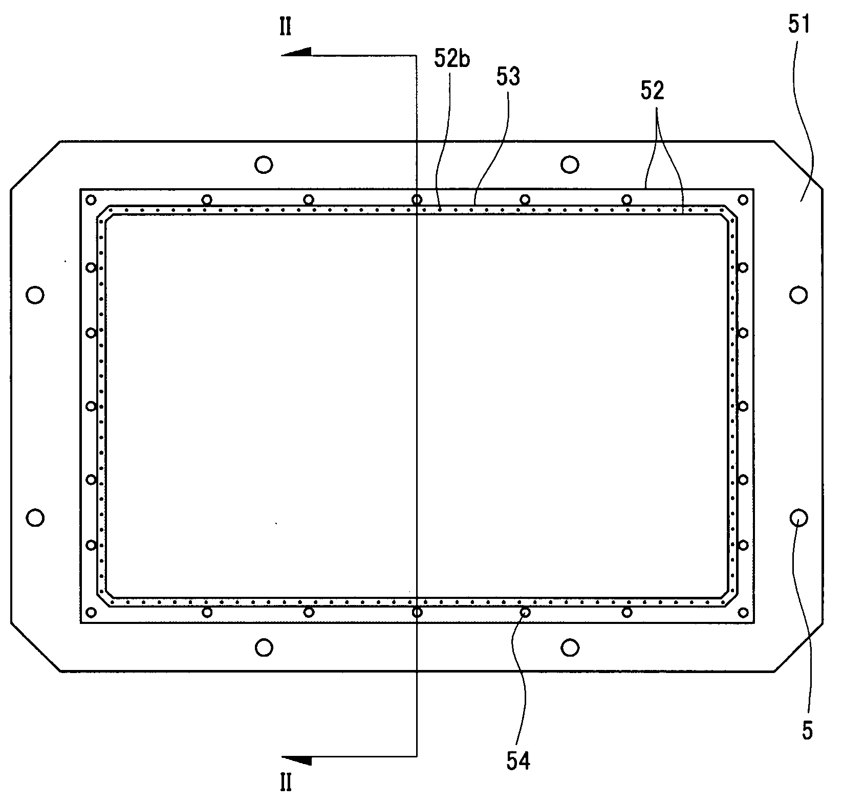
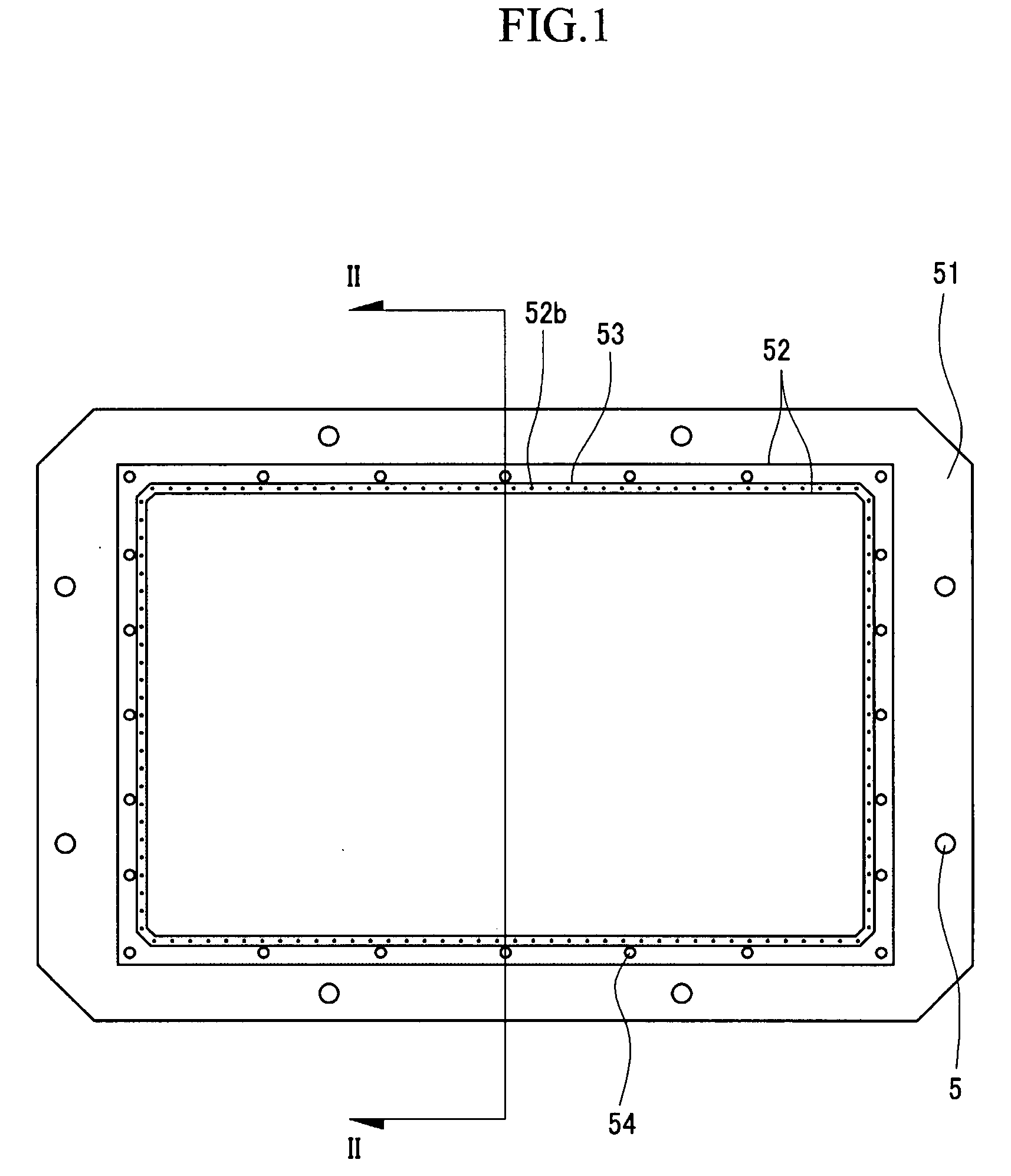
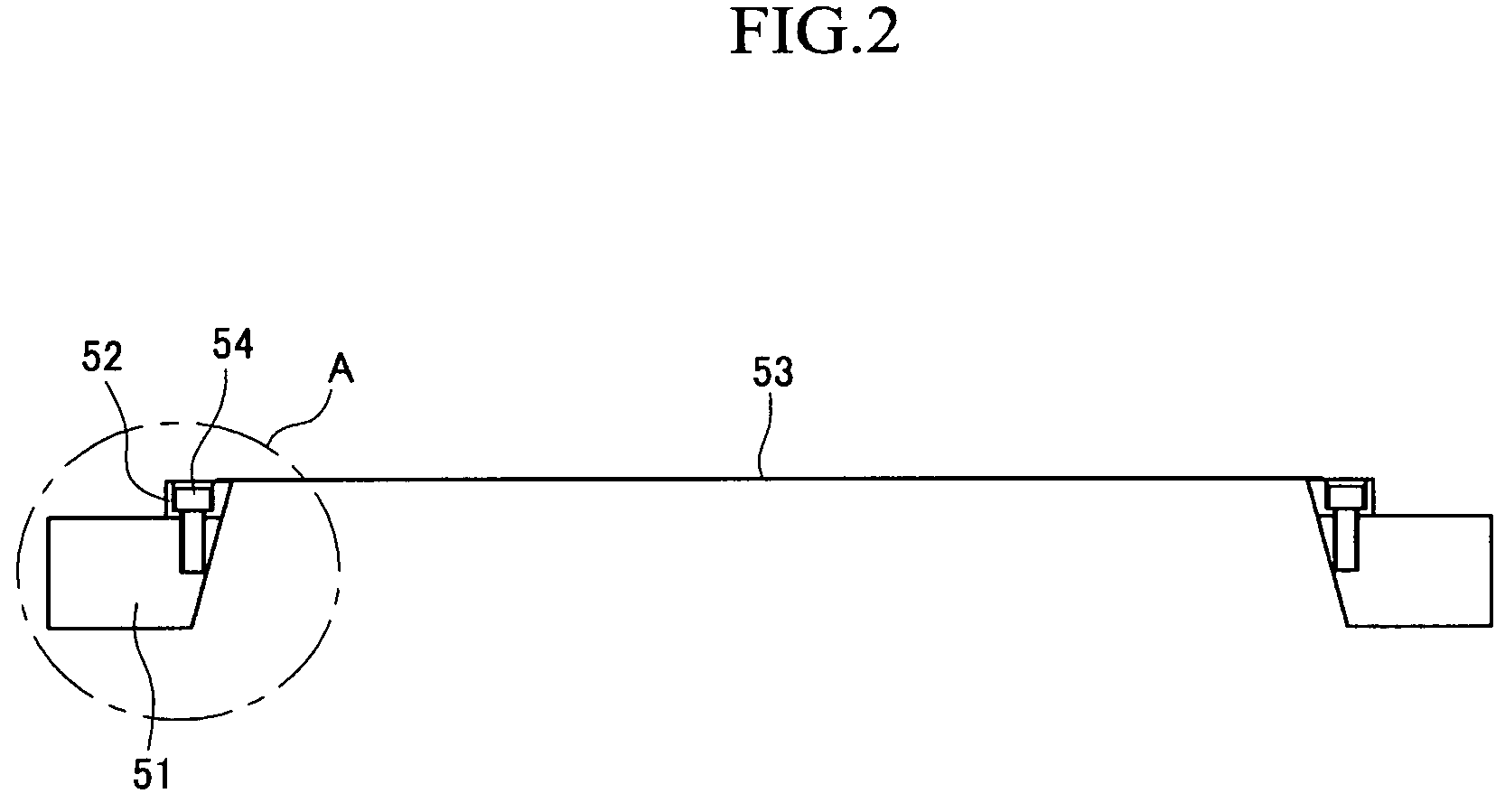
[0025]FIG. 1 is a top plan view of a shadow mask according to the exemplary embodiment of the present invention, FIG. 2 is a cross-sectional view taken along the line II-II of FIG. 1, and FIG. 3 is an enlarged view of the region A in FIG. 2.

[0026]As shown in FIGS. 1 to 3, the shadow mask according to the exemplary embodiment of the present invention includes a mask frame 51 shaped like a picture frame, a connection frame 52 fastened t...


PUM

PropertyMeasurementUnit
specific gravityaaaaaaaaaa

Abstract

A mask that facilitates OLED processing and is capable of being made cost-effectively is presented. The mask includes a mask frame, a connection frame fastened to the mask frame, a mask plate welded to the connection frame, and a plurality of fastening members that fasten the connection frame to the mask frame. The connection frame, which is capable of being welded to the mask plate, is interposed between the mask plate and the mask frame to create a tension in the mask plate. Thus, it is possible to manufacture a shadow mask that does not sag. The mask frame may be formed with a light metal such as aluminum.

Description

CROSS-REFERENCE TO RELATED APPLICATION[0001]This application claims priority to and the benefit of Korean Patent Application No. 10-2006-0015000 filed in the Korean Intellectual Property Office on Feb. 16, 2006, the entire content of which is incorporated herein by reference.BACKGROUND OF THE INVENTION[0002](a) Field of the Invention[0003]The present invention relates to a mask and a method of manufacturing the same.[0004](b) Description of the Related Art[0005]An OLED (organic light emitting display) includes two electrodes and a light emission layer interposed between the electrodes. An electron from one electrode combines with a hole from the other electrode in the light emission layer to form an exciton. The exciton emits light while emitting energy.[0006]The OLED is a self-light emitting type device that does not require a separate light source. Not needing a separate light source makes the OLED advantageous from the perspective of power consumption and enables the device to op...

Claims


Application Information

Patent Timeline
Patent Type & Authority Applications(United States)
IPC IPC(8): H01J9/12
CPCC23C14/042H01L51/56H01L51/0011C23C14/225H10K71/166H10K71/00H05B33/10
Inventor LEE, JOO-HYEONPARK, CHANG-MO
Owner SAMSUNG ELECTRONICS CO LTD
Why Eureka
Try Eureka