Snow plow dolly

a technology of snow plows and dollies, applied in the field of snow plow dolls, can solve the problems of no lateral members to prevent forward or lateral slippage, no lateral members to disclose for preventing sideways slippage of snow plow blades or snow plow jacks, and less stability during movemen

Inactive Publication Date: 2007-08-23
DOAK BERNARD A
View PDF14 Cites 5 Cited by
  • Summary
  • Abstract
  • Description
  • Claims
  • Application Information

AI Technical Summary

Benefits of technology

[0020] The invention comprises a snow plow support frame and a positioning means for moving same. The support frame is comprised of three support members formed as an isosceles triangle, with the base of the triangle directed forward and suitably adapted to support a snow plow blade, and the apex of the triangle directed rearward. A fourth support member runs from the apex of the triangle to the center of the base of the triangle; this fourth support member is suitably adapted to support a snow plow jack. In the preferred embodiment the snow plow blade support member comprises upwardly depending planar retaining members, one along the front and two at each end, to prevent the snow plow blade from slipping forward or laterally, and the snow plow jack support member comprises upwardly depending planar retaining members, one along each lateral edge, to prevent the snow plow jack from slipping laterally.
[0021] In one embodiment the positioning means comprises at least two wheels, located at either end of the snow plow blade support member. In another embodiment the positioning means comprises casters instead of wheels. In the preferred embodiment a third wheel or caster is located at the apex of the triangle formed by the support members. In an alternative embodiment a skid may be located at the apex. The wheels may incorporate wheel locks to prevent movement of the snow plow dolly when movement is not desired. In the most preferred embodiment the wheels depend downward from lateral outriggers attached to the support frame at the corners of the triangle of the support frame, whereby the outriggers allow the support frame to be located below the tops of the wheels, thereby lowering the center of gravity of the device and making it more stable when positioning a snow plow.

Problems solved by technology

It also has no lateral members for preventing a snow plow from sliding off.
There are no members for preventing forward or lateral slippage.
Many of the disclosed devices comprise complicated mechanisms for adjusting the height of the snow plow supports.
While some of the prior art discloses various means for preventing forward slippage of the snow plow blade, none discloses lateral members for prevention of sideways slippage of the snow plow blade or the snow plow jack.
Most position the wheels or casters directly beneath the frame, thereby providing a higher center of gravity and less stability during movement.
None of the prior art discloses a simple, inexpensive snow plow dolly having a low center of gravity for stability and front and lateral support members for securing a snow plow thereon without risk of front or lateral slippage during movement.

Method used


Image

  • Snow plow dolly
  • Snow plow dolly
  • Snow plow dolly

Examples


Embodiment Construction

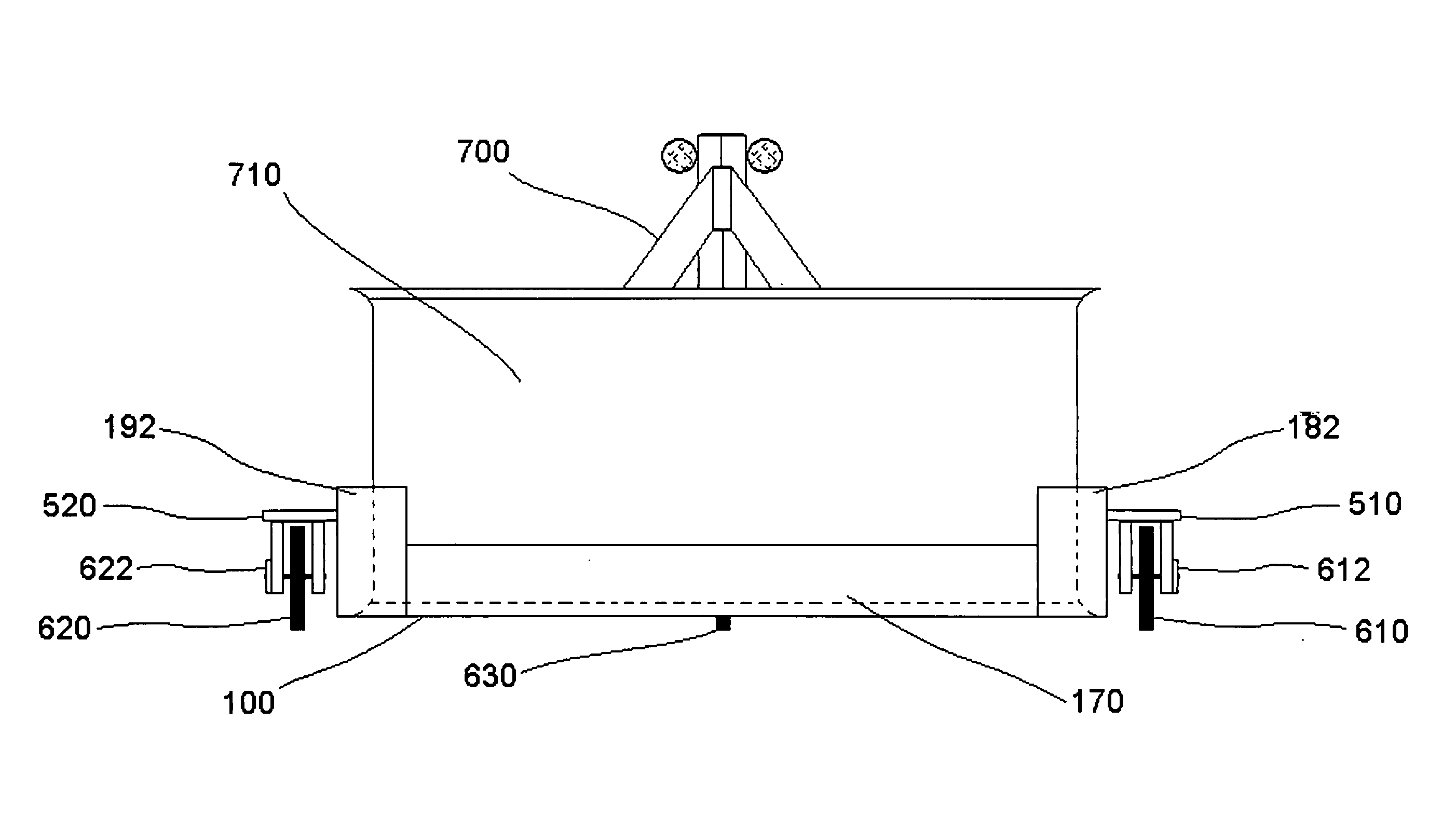
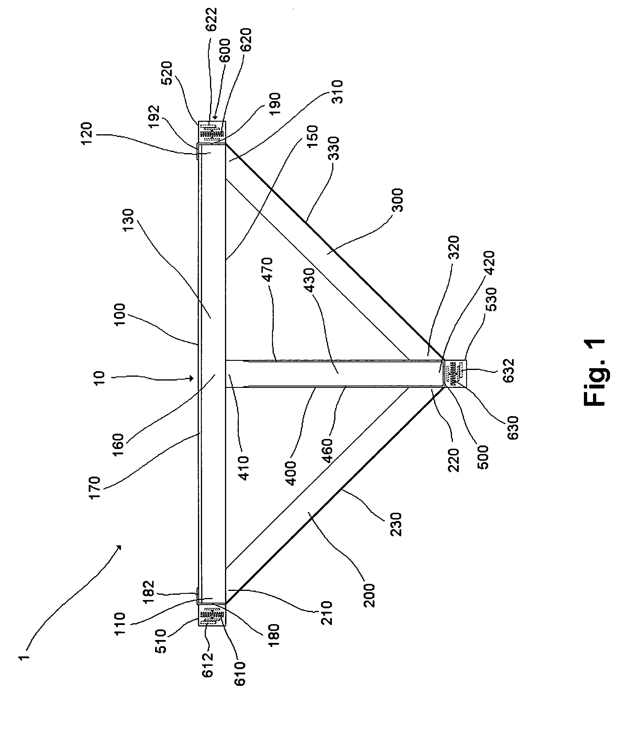
[0028] The improved snow plow dolly 1 of the present invention is intended to be used to support and position a standard snow plow 700, when the snow plow 700 is detached from its carrying vehicle. The snow plow 700 must have at least a snow plow blade 710 and a snow plow jack 720, with the snow plow jack 720 located along an axis substantially perpendicular with the plane of the snow plow blade 710. See FIG. 4. The present invention comprises two principal components, each presenting an improvement over the prior art: the support frame 10 and the positioning means 600. The support frame 10 is comprised of four subcomponents: the blade support member 100, two lateral support members 200,300, and the jack support member 400. See FIG. 1. The four subcomponents should be made of a structurally sturdy and rigid material. The preferred material is steel.

[0029] The blade support member 100 is an elongate beam oriented substantially horizontally in a plane substantially parallel to the gr...


PUM


Abstract

An improved snow plow dolly having a low center of gravity for improved stability when supporting a snow plow, together with front and lateral support members to retain the snow plow in place during movement.

Description

BACKGROUND OF THE INVENTION [0001] 1. Technical Field [0002] The invention relates generally to the field of snow plow dollies. More specifically, the invention is directed to an improved snow plow dolly employing a simple yet sturdy construction that securely retains a snow plow thereon. [0003] 2. Description of Prior Art [0004] Snow plow dollies are well known in the art. All disclose a support frame for supporting the snow plow blade and snow plow jack, and positioning means, typically wheels but also casters, for maneuvering the snow plow blade once it has been placed on the dolly and detached from the carrying vehicle. Many also disclose adjustment means for accommodating different height snow plow jacks. [0005] Buttner, U.S. Pat. No. 3,941,400 (Mar. 2, 1976), “Plow Dolly”, discloses a triangular steel dolly supported by casters located directly beneath each corner. The snow plow blade is supported by a V-channel attached to the top of the shorter side. A horizontally and verti...

Claims


Application Information

Patent Timeline
Patent Type & Authority Applications(United States)
IPC IPC(8): E01H5/06
CPCB62B1/002E01H5/066B62B3/12
Inventor DOAK, BERNARD A.
Owner DOAK BERNARD A
Why Eureka
Try Eureka