
Z offset MEMS device

a technology of offset and mems, applied in the direction of simultaneous indication of multiple variables, gearing, instruments, etc., can solve the problems of costing more money, more steps and additional processing layers, and extra masks and etches

Active Publication Date: 2007-08-23
HONEYWELL INT INC
View PDF17 Cites 9 Cited by
  • Summary
  • Abstract
  • Description
  • Claims
  • Application Information

AI Technical Summary

Problems solved by technology

Deflecting with stiction plates leads to devices which are sensitive to z motion, but is not easily implemented for multiple z-offsets in both directions and also requires more steps and additional processing layers, thereby costing more money.
Selective thinning is performed by thinning one set of teeth in the Z-direction, but this requires an extra mask and additional etches, and it is also rather inaccurate.

Method used


Image

  • Z offset MEMS device
  • Z offset MEMS device
  • Z offset MEMS device

Examples


Embodiment Construction

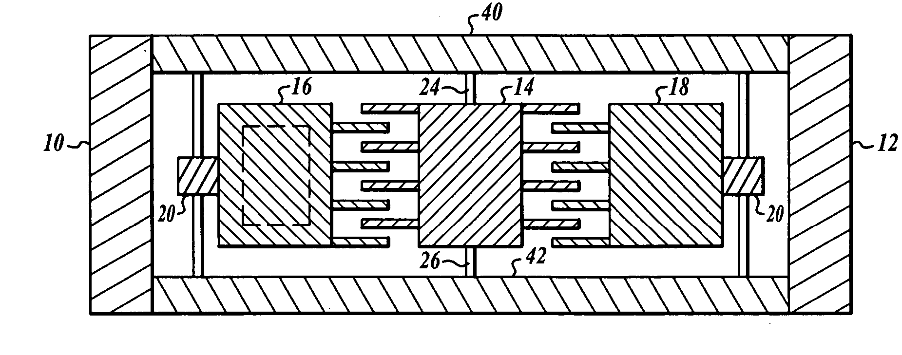
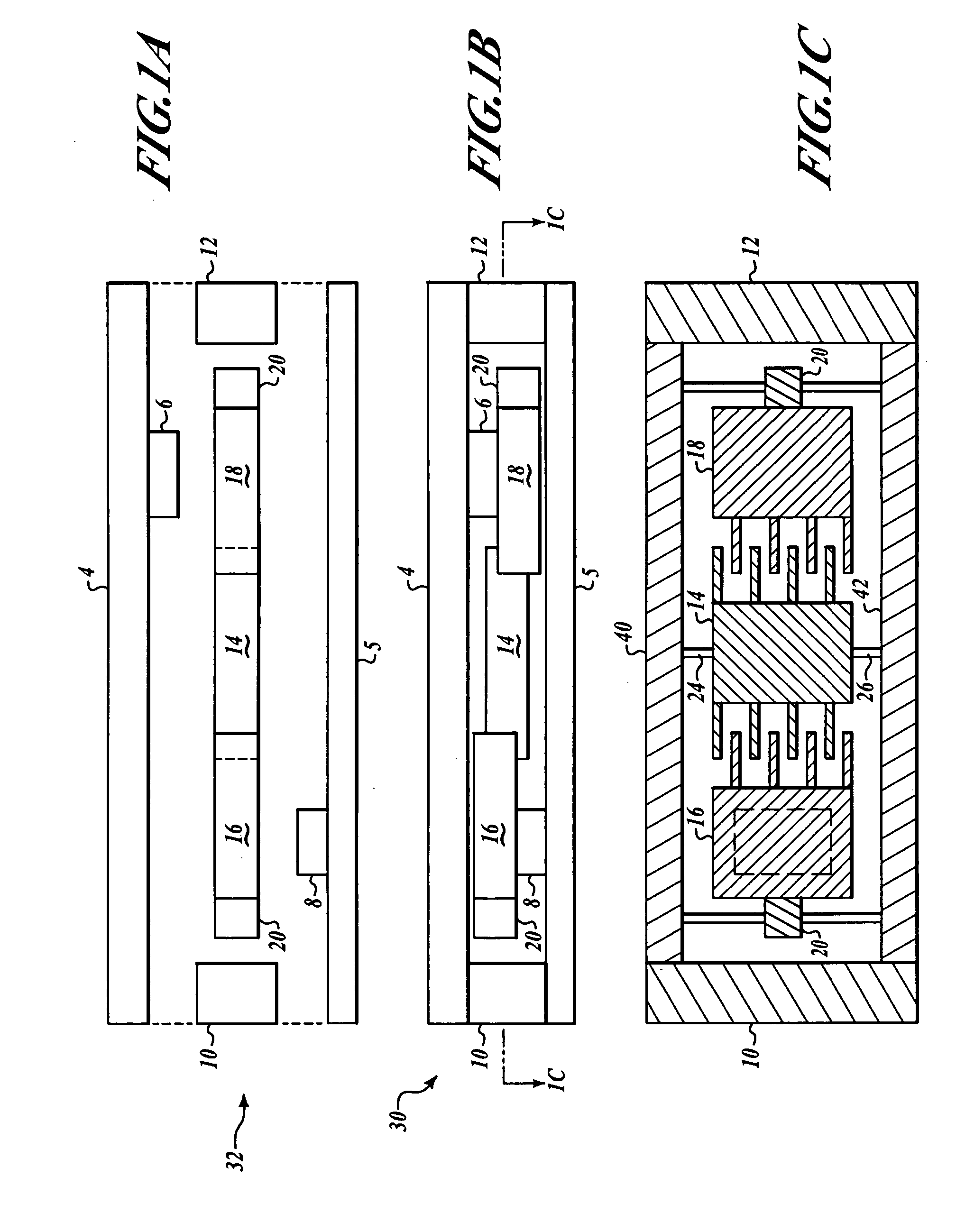
[0008]FIGS. 1A, 1B and 1C illustrate a side view before assembly, a side view after assembly and a top view of a microelectromechanical system (MEMS) comb structure device 30 formed in accordance with one embodiment of the invention. FIGS. 1A and 1B show that the device 30 has a top cover 4 and a bottom cover 5 enclosing a mechanism layer 32 that includes a first side 10, a second side 12 directly opposite the first side 10, a movable part 14, a first fixed part 16, a second fixed part 18, and flexures 20. Flexures may also be referred to as torsional flexures or as hinges. FIG. 1A illustrates a cross-sectional side view of the comb structure device 30 shown in FIG. 1B before the top cover 4 and the bottom cover 5 have been attached to the device 30. For purposes of FIGS. 1B and 1C, the positive z direction is defined to run from the bottom cover 5 to the top cover 4 such that it is orthogonal to the outer surfaces of both of the covers and orthogonal to the mechanism layer. The top...


PUM


Abstract

A microelectromechanical system (MEMS) device with a mechanism layer having a first part and a second part, and at least one cover for sealing the mechanism layer. The inner surface of at least one of the covers is structured such that a protruding structure is present on the inner surface of the cover and wherein the protruding structure mechanically causes the first part to be deflected out of a plane associated with the second part.

Description

BACKGROUND OF THE INVENTION [0001] Standard microelectromechanical systems (MEMS) processing techniques create structures that are symmetric in the z axis (out of the wafer's surface) but can vary in the x and y axes (in the plane of the wafer's surface). This leads to devices which can only move in the x / y plane. Presently, creating asymmetry in the z-axis can be performed by deflecting with stiction plates or by selective thinning. Deflecting with stiction plates leads to devices which are sensitive to z motion, but is not easily implemented for multiple z-offsets in both directions and also requires more steps and additional processing layers, thereby costing more money. Selective thinning is performed by thinning one set of teeth in the Z-direction, but this requires an extra mask and additional etches, and it is also rather inaccurate. [0002] Thus, there exists a need for methods to easily form z-offsets in MEMS devices. BRIEF SUMMARY OF THE INVENTION [0003] A microelectromecha...

Claims


Application Information

Patent Timeline
Patent Type & Authority Applications(United States)
IPC IPC(8): B81B3/00G01D5/12G01D5/00G01P15/13
CPCB81B7/0077B81B2201/033Y10T74/22G01P15/125G01P15/18G01P15/0802
Inventor KLEIN, JONATHAN L.MAGENDANZ, GALEN P.LAFOND, PETER H.WILLIAMS, MARK L.FOSTER, MICHAEL J.
Owner HONEYWELL INT INC
Learn More