Zoom lens system and optical device using thereof

a zoom lens and optical device technology, applied in the field of zoom lens systems and optical devices, can solve problems such as image blur and deterioration of imaging performance, and achieve the effect of high optical performan

Inactive Publication Date: 2007-08-23
NIKON CORP
View PDF7 Cites 33 Cited by
  • Summary
  • Abstract
  • Description
  • Claims
  • Application Information

AI Technical Summary

Benefits of technology

[0010]The present invention is made in view of the aforementioned problems and has an object to provide a zoom lens system having a vibration reduction function, a high optical performance, and an ultra-compactness, suitable for a compact optical device using a solid-state imaging device, and the like, and another object to provide an optical device using the zoom lens system.
[0019]According to a third aspect of the present invention, there is provided a method for forming an image of an object and varying a focal length of a zoom lens system, the method comprising steps of: providing the zoom lens system that includes, in order from an object along an optical axis, a first lens group having positive refractive power and an optical path bending member for bending the optical path by substantially 90 degrees, a second lens group having negative refractive power, a third lens group having positive refractive power, and a fourth lens group having positive refractive power; varying the focal length of the zoom lens system from a wide-angle end state to a telephoto end state by fixing the first lens group and the third lens group with respect to an image plane, moving the second lens group to the image plane, and moving the fourth lens group at first to the object and then to the image plane; and correcting an image blur on the image plane upon generating the camera shake by moving the third lens group in a direction perpendicular to the optical axis.

Problems solved by technology

In such a zoom lens system, there has been a problem that a minute camera shake generated upon shooting such as a camera shake generated when a photographer presses a shutter release button causes an image blur to deteriorate imaging performance.

Method used


Image

  • Zoom lens system and optical device using thereof
  • Zoom lens system and optical device using thereof
  • Zoom lens system and optical device using thereof

Examples


first embodiment

[0081]A zoom lens system according to a first embodiment is explained.

[0082]A zoom lens system according to the first embodiment is composed of, in order from an object, a first lens group having positive refractive power and an optical path bending member for bending the optical path by substantially 90 degrees, a second lens group having negative refractive power, a third lens group having positive refractive power, and a fourth lens group having positive refractive power. When the focal length varies from a wide-angle end state to a telephoto end state, which is called as zooming, the first lens group and the third lens group are fixed with respect to an image plane, the second lens group is moved to the image, and the fourth lens group is moved at first to the object and then to the image plane such that a distance between the first lens group and the second lens group increases, and a distance between the second lens group and the third lens group decreases. Upon generating a c...

example 1

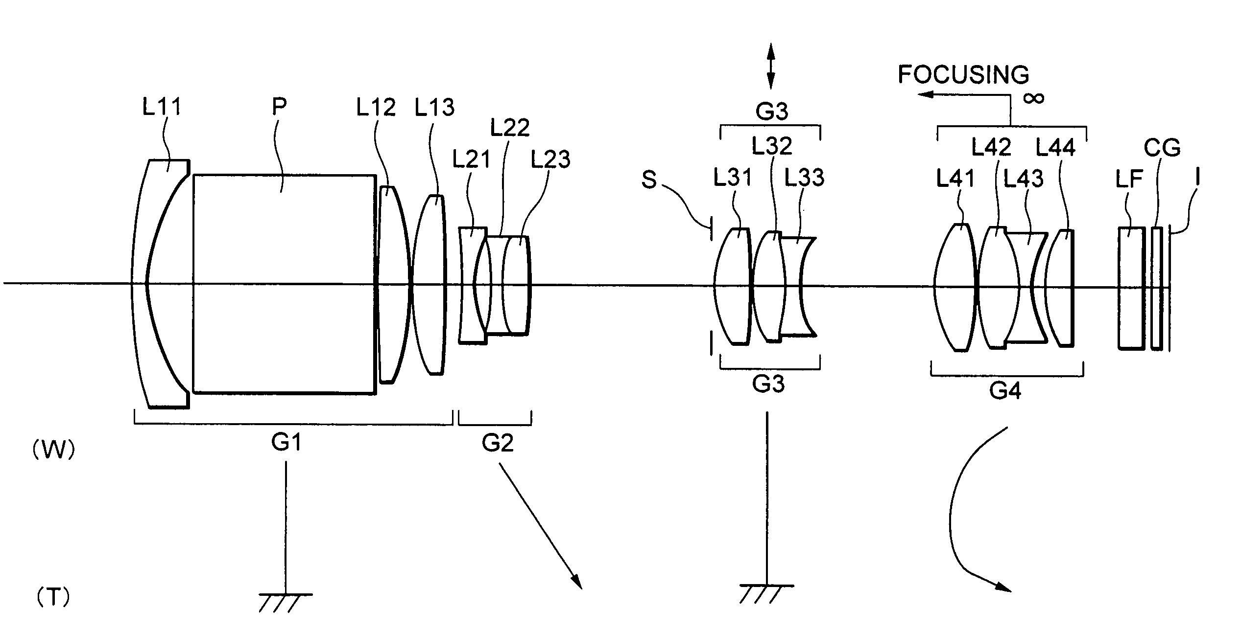
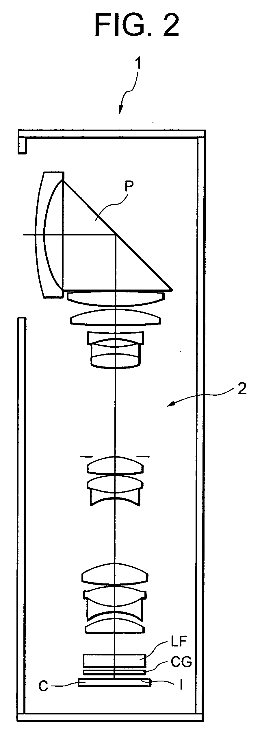
[0105]FIG. 3 is a diagram showing a lens configuration of a zoom lens system according to Example 1 of the first embodiment. Although the zoom lens system according to Example 1 deflects its optical path by 90 degrees as shown in FIG. 2, the optical path is extended in FIG. 3.

[0106]In FIG. 3, the zoom lens system according to Example 1 is composed of, in order from an object, a first lens group G1 having positive refractive power and a rectangular prism P for bending the optical path by 90 degrees, the second lens group G2 having negative refractive power, a third lens group G3 having positive refractive power, and a fourth lens group G4 having positive refractive power. When the focal length varies from a wide-angle end state W to a telephoto end state T, the first lens group G1 and the third lens group G3 are fixed with respect to the image plane I, the second lens group G2 is moved to the image plane I, and the fourth lens group G4 is moved at first to the object and then to the ...

example 2

[0119]FIG. 8 is a diagram showing a lens configuration of a zoom lens system according to Example 2 of the first embodiment. Although the zoom lens system according to Example 2 deflects its optical path by 90 degrees as shown in FIG. 2, the optical path is extended in FIG. 8.

[0120]In FIG. 8, the zoom lens system according to Example 2 is composed of, in order from an object, a first lens group G1 having positive refractive power and a rectangular prism P for bending the optical path by 90 degrees, the second lens group G2 having negative refractive power, a third lens group G3 having positive refractive power, and a fourth lens group G4 having positive refractive power. When the focal length varies from a wide-angle end state W to a telephoto end state T, the first lens group G1 and the third lens group G3 are fixed with respect to the image plane I, the second lens group G2 is moved to the image plane I, and the fourth lens group G4 is moved at first to the object and then to the ...


PUM


Abstract

Providing an ultra-compact zoom lens system having a vibration reduction function, suitable for a compact optical device using a solid-state imaging device. The system includes, in order from an object, a first lens group having positive power and a bending member for bending the optical path by about 90°, a second lens group having negative power, a third lens group having positive power, and a fourth lens group having positive power. Upon zooming from a wide-angle end state to a telephoto end state, the first and third lens groups are fixed with respect to an image plane, the second lens group is moved to the image, and the fourth lens group is moved at first to the object and then to the image plane. An image blur on the image plane caused by a camera shake is corrected by moving the third lens group perpendicularly to the optical axis.

Description

[0001]The disclosure of the following priority applications are herein incorporated by reference:[0002]Japanese Patent Application No. 2006-041510 filed on Feb. 17, 2006, and[0003]Japanese Patent Application No. 2006-041515 filed on Feb. 17, 2006.BACKGROUND OF THE INVENTION[0004]1. Field of the Invention[0005]The present invention relates to a zoom lens system and an optical device using thereof.[0006]2. Related Background Art[0007]There has been proposed a bended zoom lens system (hereinafter simply called as a zoom lens system) suitable for a camera using a solid-state imaging device and the like, having a zoom ratio of about three to seven by using a rectangular prism for bending an optical path within the camera (for example, Japanese Patent Application Laid-Open No. 2005-215165).[0008]In such a zoom lens system, there has been a problem that a minute camera shake generated upon shooting such as a camera shake generated when a photographer presses a shutter release button causes...

Claims


Application Information

Patent Timeline
Patent Type & Authority Applications(United States)
IPC IPC(8): G02B15/14
CPCG02B5/04G02B27/646G02B15/177G02B15/173G02B15/144113
Inventor ARAI, DAISAKU
Owner NIKON CORP
Why Eureka
Try Eureka