Brightness correction apparatus for moving images, and method and program for controlling same

Active Publication Date: 2007-08-23
FUJIFILM CORP
View PDF4 Cites 8 Cited by
  • Summary
  • Abstract
  • Description
  • Claims
  • Application Information

AI Technical Summary

Benefits of technology

[0010]According to the present invention, a number of frames of subject images are applied in succession one frame at a time at a fixed period, and a target-image portion is detected from within one subject image. A still-image brightness correction parameter is calculated based upon the brightness of the target-image portion detected. On the basis of another subject image earlier than the one subject image, an adjustment parameter for adjusting (correcting) the still-image brightness correction parameter is calculated. A moving-image correction parameter is calculated by adjusting the still-image brightness correction parameter using the adjustment parameter calculated. The brightness of a correction-target subject image, which is later than the one subject image, is corrected using the moving-image correction parameter that has been calculated. Thus, the brightness of the correction-target subject image is corrected taking into consideration the brightness of the subject image of a preceding frame and the brightness of the target-image portion. The target-image portion of the correction-target subject image takes on a comparatively appropriate brightness, and it is possible to prevent a sudden change in brightness also in a case where a moving image is viewed as a whole.
[0013]It is preferred that the moving-image brightness correction parameter, which is calculated by the moving-image brightness correction parameter calculating device, fall within a fixed range that starts from the adjustment parameter calculated by the adjustment parameter calculating device. This makes it possible to prevent a sudden fluctuation in brightness.

Problems solved by technology

However, this correction is premised on the image being a still image and does not take moving images into consideration.
Further, although there is prior art that applies a tone correction to a moving image (see the specification of Japanese Patent Application Laid-Open No. 2005-204195), this does not take into account a specific target-image portion of the image of a subject, such as a face image.
Consequently, there are occasions where a specific target-image portion appears too dark.

Method used


Image

  • Brightness correction apparatus for moving images, and method and program for controlling same
  • Brightness correction apparatus for moving images, and method and program for controlling same
  • Brightness correction apparatus for moving images, and method and program for controlling same

Examples


Embodiment Construction

[0032]Preferred embodiments of the present invention will now be described in detail with reference to the drawings.

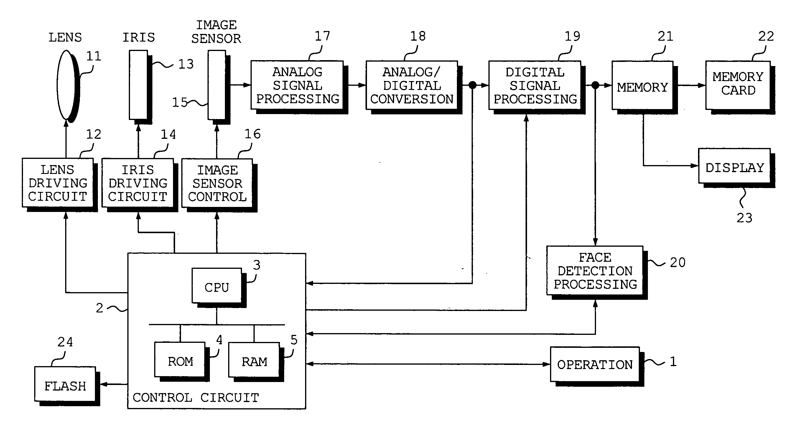
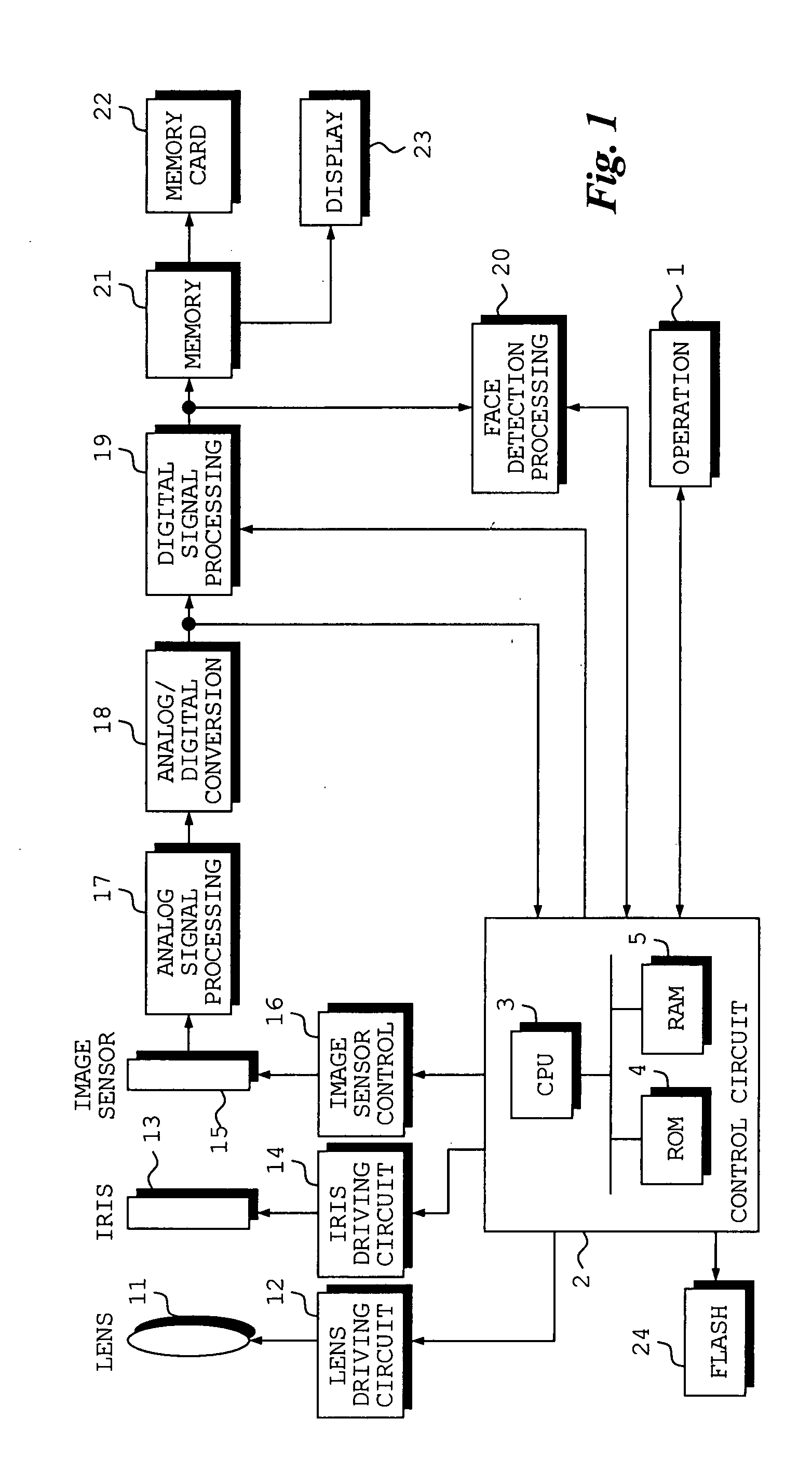
[0033]FIG. 1, which illustrates an embodiment of the invention, is a block diagram illustrating the electrical structure of a digital still camera.

[0034]The overall operation of the digital still camera is controlled by a control circuit 2. The latter includes a CPU 3, a ROM 4 and a RAM 5, which are interconnected by a bus. The digital still camera includes operating buttons 1 such as a shutter-release button of two-step stroke type, a power button, a mode setting dial, a menu button, a decide button and a so-called cross-hair button formed in such a manner that up, down, left and right arrows can be pressed. Output signals from the operating buttons 1 are input to the control circuit 2. Also connected to the control circuit 2 is a unit 24 for emitting an electronic flash when the amount of exposure falls below a fixed amount.

[0035]If an image sensing mode is set, ligh...


PUM


Abstract

In order to perform a brightness correction that is suited to a face image in a moving image, a still-image brightness correction parameter for performing a brightness correction suited to a subject image is calculated from a face image in the subject image and the overall subject image. A moving-image brightness correction parameter is calculated using the calculated still-image brightness correction parameter and a moving-image brightness correction parameter that has been calculated in a subject image of a previous frame. By using the moving-image brightness correction parameter calculated, the brightness of a subject image obtained subsequent to the first-mentioned subject image is corrected.

Description

BACKGROUND OF THE INVENTION[0001]1. Field of the Invention[0002]This invention relates to an apparatus for correcting the brightness of a moving image, and to a method and program for controlling this apparatus.[0003]2. Description of the Related Art[0004]When the image of a subject is sensed, a tone correction is performed in such a manner that the portion of the image of the subject that is the main subject image will have an appropriate brightness (see the specification of Japanese Patent Application Laid-Open No. 2005-159650). However, this correction is premised on the image being a still image and does not take moving images into consideration.[0005]Further, although there is prior art that applies a tone correction to a moving image (see the specification of Japanese Patent Application Laid-Open No. 2005-204195), this does not take into account a specific target-image portion of the image of a subject, such as a face image. Consequently, there are occasions where a specific t...

Claims


Application Information

Patent Timeline
IPC IPC(8): G03B7/08G06T5/00H04N5/238H04N101/00
CPCG03B7/08H04N5/2351H04N5/235H04N23/71H04N23/70
Inventor SUGIMOTO, MASAHIKO
Owner FUJIFILM CORP
Why Eureka
Try Eureka