LED lamp apparatus for vehicles

Inactive Publication Date: 2005-03-22
TOYODA GOSEI CO LTD
View PDF9 Cites 63 Cited by
  • Summary
  • Abstract
  • Description
  • Claims
  • Application Information

AI Technical Summary

Benefits of technology

Thus, an LED head lamp apparatus for vehicles can be provided wherein emitted light brightness can be homogenized among light emitting diodes, a fluct

Problems solved by technology

This necessitates troublesome wiring work and incurs higher cost.
An additional problem of the conventional technique is that, when the current limiting circuit 55 is a resistor, a fluctuation in power supply

Method used


Image

  • LED lamp apparatus for vehicles
  • LED lamp apparatus for vehicles
  • LED lamp apparatus for vehicles

Examples


first embodiment

(First Embodiment)

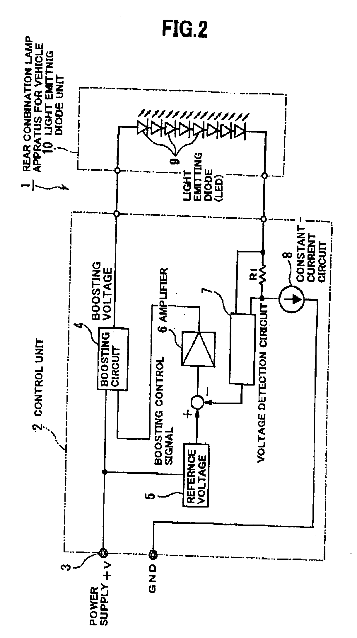
First embodiment of the invention will be explained in conjunction with FIGS. 2 and 3. FIG. 2 is a schematic circuit diagram showing a circuit in a rear combination lamp apparatus for vehicles in first embodiment of the invention. FIG. 3 is a circuit diagram showing, in more detail, the circuit in the rear combination lamp apparatus for vehicles in the first embodiment of the invention.

As shown in FIG. 2, a rear combination lamp apparatus 1 for vehicles in this embodiment of the invention includes a control unit 2 and a light emitting diode unit 10. In this LED unit 10, all of eight LEDs 9 are connected in series to constitute a rear combination lamp. The voltage of a power supply 3, that is, a battery of a vehicle, is about 12 V, while the LED unit 10 requires about 16 V (about 2 V×8=about 16 V). Therefore, a shortage of voltage occurs. To cope with this, a boosting circuit 4 is provided within the control unit 2 to boost the voltage to about 16 V which is then ap...

second embodiment

(Second Embodiment)

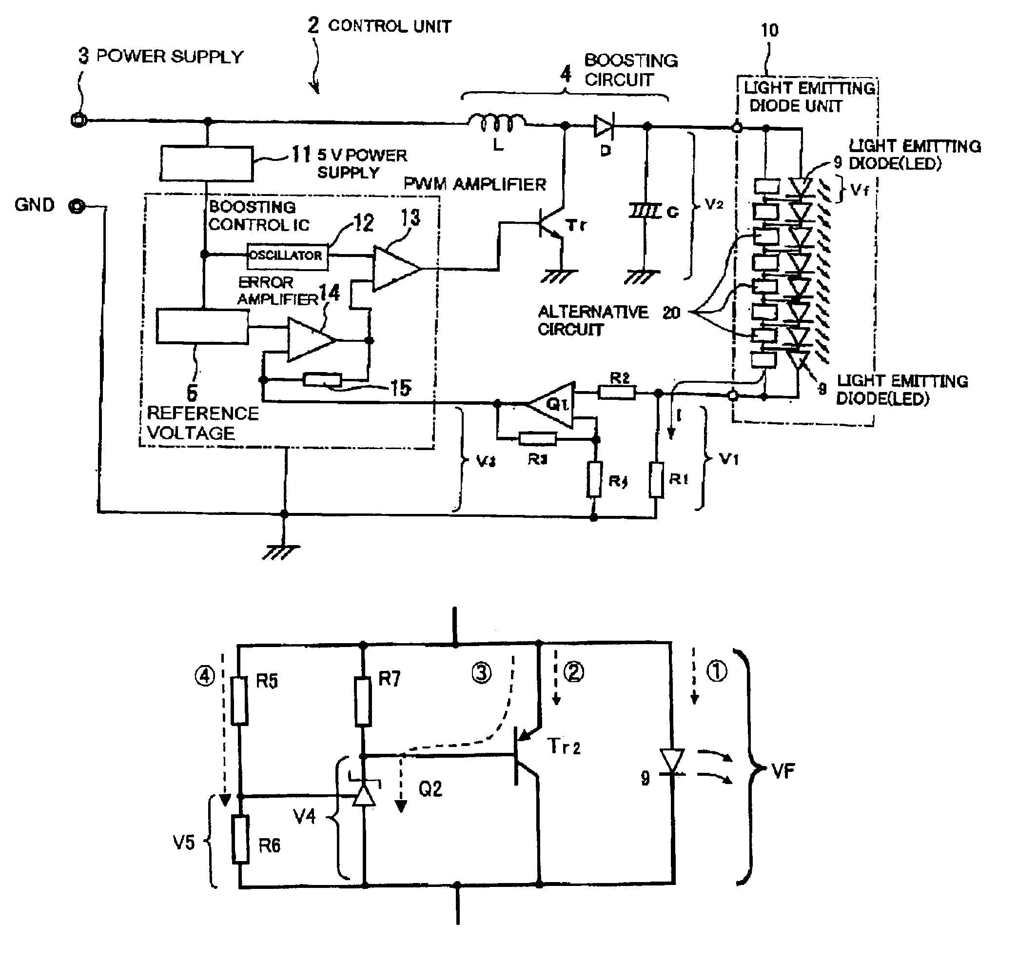
A second embodiment of the invention will be explained in conjunction with FIGS. 4-6. FIG. 4 is a schematic circuit diagram showing a circuit in an LED head lamp apparatus for vehicles in the second embodiment of the invention. FIG. 5 is a circuit diagram showing, in more detail, the circuit in the LED head lamp apparatus for vehicles in the second embodiment of the invention. FIG. 6 is a schematic diagram showing a circuit of each LED 9 in an LED head lamp apparatus for vehicles in the second embodiment of the invention.

As shown in FIGS. 4 and 5, an LED head lamp apparatus 30 for vehicles in this embodiment of the invention is similar to the first embodiment with the exception that in this LED unit 10, an alternate circuit 20 for coping with disconnection is provided in each of the eight LEDs 9 connected in series. Therefore, in FIGS. 4 and 5, parts similar to those previously described with reference to FIGS. 2 and 3 are denoted by the same reference numerals, a...


PUM


Abstract

In an LED unit, all of eight LEDs are connected in series. The voltage of a power supply, that is, a battery of a vehicle, 12 V, is insufficient for the eight LEDs. To cope with this, a boosting circuit is provided within the control unit to boost the voltage to about 16 V which is then applied to the eight LEDs. The front end of the LED unit is connected to a constant-current circuit, and a voltage detection circuit is provided near and connected to this constant-current circuit for detecting the voltage applied to the constant-current circuit. The voltage detected by the voltage detection circuit is compared with a reference voltage drawn from the power supply, is amplified in an amplifier, and is input as a boosting control signal into the boosting circuit. The boosting control signal is output so as to regulate the boosted voltage in such a manner that the voltage detected in the voltage detection circuit is a lowest possible voltage.

Description

The present application is based on Japanese Patent Applications No.2001-386371 and No.2002-212633, the entire contents of which are incorporated herein by reference.BACKGROUND OF THE INVENTION1. Field of the InventionThis invention relates to an LED lamp apparatus such as a rear combination lamp apparatus and an LED head lamp apparatus for vehicles, which controls an LED lamp for vehicles using light emitting diodes as a light source.In this specification, an LED chip per se is referred to as “light emitting device,” and the whole system including an LED chip-mounted package resin or lens system or other optical system is referred to as “light emitting diode” or “LED.”2. Related ArtAn increase in brightness of light emitting devices has led to extensive use of an LED lamp such as a rear combination lamp and an LED head lamp for vehicles using LEDs as a light source, for example, in stop lamps of automobiles. LEDs have a narrow-band emission spectrum, and the emitted light has good ...

Claims


Application Information

Patent Timeline
IPC IPC(8): H05B33/02H05B33/08H05B44/00
CPCH05B33/0815H05B33/0851H05B33/0821H05B45/40H05B45/10H05B45/38H05B45/48B60Q1/1407
Inventor TANABE, TETSHUOTAUCHI, SHIGEAKI
Owner TOYODA GOSEI CO LTD
Why Eureka
Try Eureka