Electric mover for swing away conveyor

a technology of electric mover and conveyor, which is applied in the direction of electric digital data processing, control devices of conveyors, instruments, etc., can solve the problems of dependability of these systems

Inactive Publication Date: 2014-11-20
BRANDT AGRI PROD LTD
View PDF13 Cites 12 Cited by
  • Summary
  • Abstract
  • Description
  • Claims
  • Application Information

AI Technical Summary

Benefits of technology

[0009]The present disclosure provides an electric drive apparatus for a swing away auger assembly that with a sealed circuit housing that dissipates heat generated by electrical components through a heat sink that forms an external wall of the housing, and thus transfers heat from the interior of the housing to the exterior thereof. The electrical components can be selected to minimize heat generated in the circuit housing as well, using CMOS technology, “soft start” operation, and heavy copper bar conductors.
[0010]The present disclosure also provides a bin level spill prevention system which will close off the flow of granular products into the conveyor when the bin is full.

Problems solved by technology

Electric motors and the circuits controlling them are prone to problems with moisture, overheating, and the like, and so dependability of these systems is problematic.

Method used


Image

  • Electric mover for swing away conveyor
  • Electric mover for swing away conveyor
  • Electric mover for swing away conveyor

Examples


Embodiment Construction

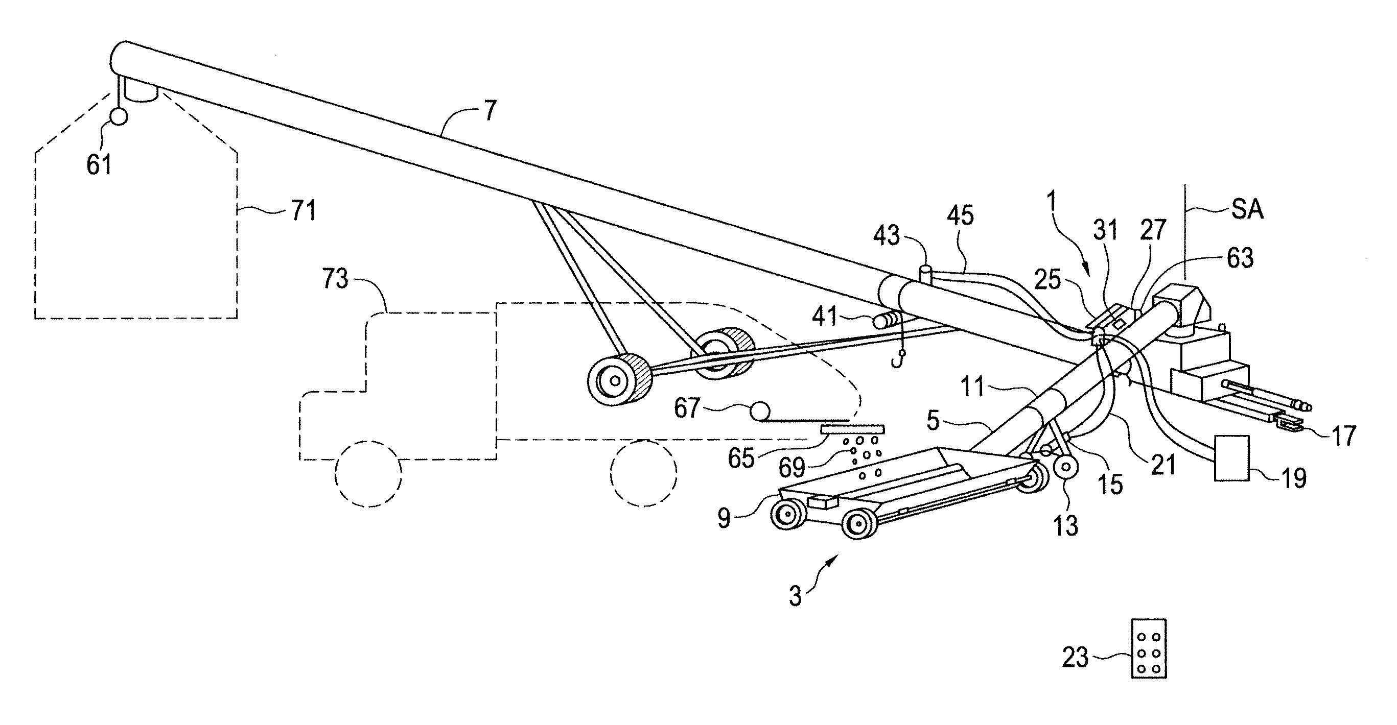
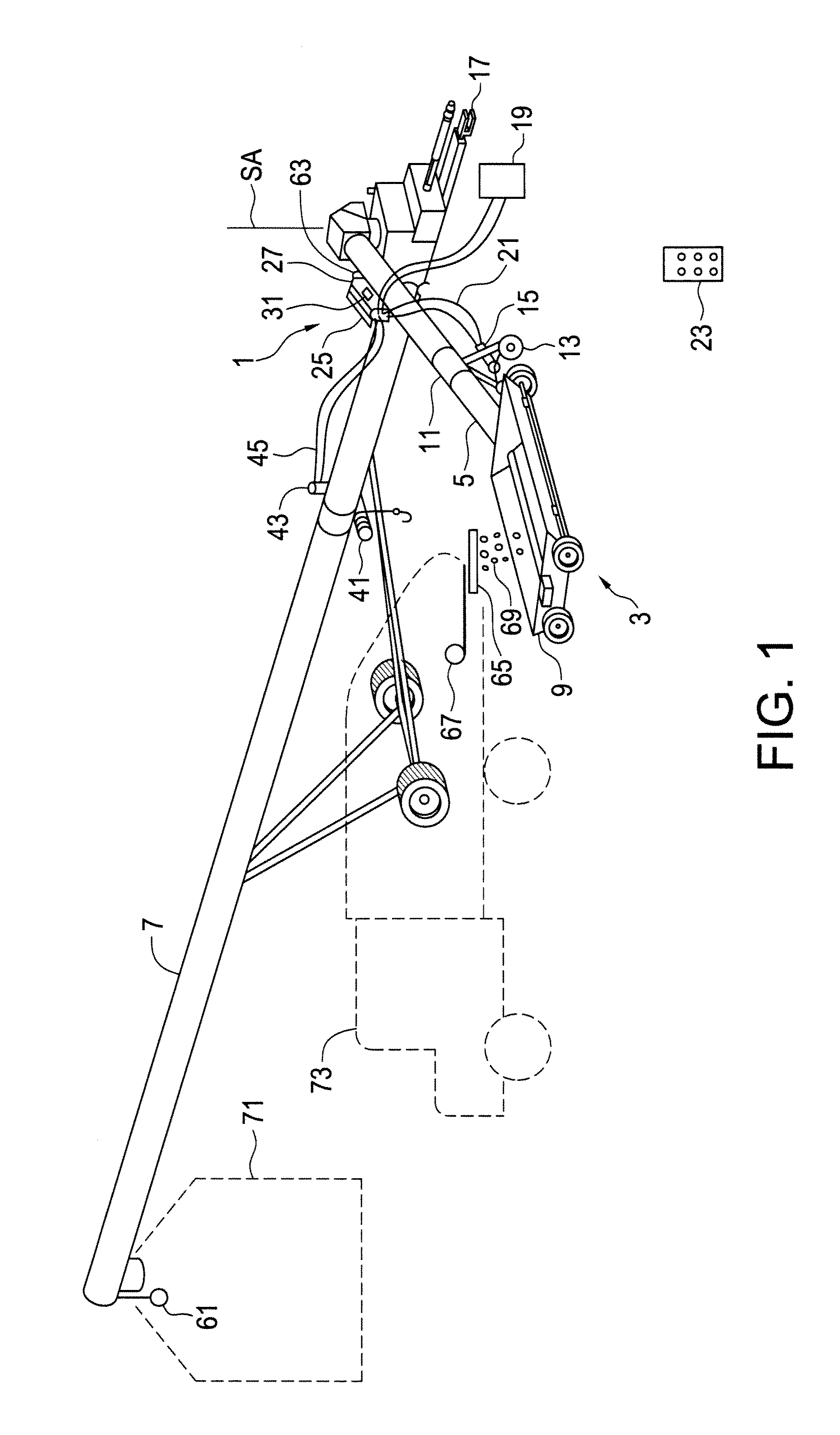
[0018]FIG. 1 illustrates an embodiment of an electric drive apparatus 1 of the present disclosure for attachment to a swing away auger assembly 3. The swing away auger assembly 3 comprises a swing auger 5 pivotally connected at an upper discharge end thereof to a lower intake end of a main conveyor 7 about a substantially vertical swing axis SA, and a hopper 9 mounted to a lower intake end of the swing auger 5.

[0019]The electric drive apparatus 1 comprises a bracket assembly 11 adapted to be attached to the swing away auger assembly 3, and a drive wheel 13 mounted to the bracket 11. The bracket assembly 11 and drive wheel 13 are configured to pivot an attached swing auger 5 about the swing axis SA as is known in the prior art. The bracket 11 and drive wheel 13 are shown mounted to the swing auger 5, however it is also known to mount a drive wheel or wheels directly to the hopper 9. An electric drive motor 15 is connected to rotate the drive wheel 13. The main conveyor 7 has a hitch ...


PUM


Abstract

An electric drive apparatus for attachment to a swing away auger assembly includes a bracket and drive wheel adapted to be attached to the assembly and configured to pivot an attached swing auger. An electric drive motor rotates the drive wheel, and a control circuit assembly is connected to the electric drive motor by drive wires. The control circuit assembly is operative to activate the electric drive motor in response to forward, stop, and reverse drive signals received from a remote control unit. The control circuit is mounted to a heat sink plate such that heat generated in the control circuit assembly is conducted to the heat sink plate, and the heat sink plate forms an external wall of a circuit housing enclosing the control circuit assembly. The circuit housing is sealed. A bin spill prevention system has a sensor that shuts a discharge gate directing material into the conveyor.

Description

[0001]This disclosure relates to the field of agricultural implements and in particular conveyors for moving agricultural products.BACKGROUND[0002]In the agricultural industry, granular products such as crop seeds, fertilizer, and the like are commonly moved from transport to storage, and vice versa, by belt and auger conveyors powered by an attached tractor. In a typical operation the conveyors are inclined to receive products at the lower end, such as from a truck, and carry them to an elevated location, such as a bin fill opening.[0003]One popular type of conveyor includes a short intake conveyor, commonly called a swing away auger, at the lower end that is pivotally attached at an inner end thereof to the bottom intake end of a main conveyor. A hopper on the outer end of the swing away auger receives product from a truck and transfers same to the intake of the main conveyor. The pivotal attachment allows the hopper to be moved under the discharge chute of a trailer carrying agri...

Claims


Application Information

Patent Timeline
Patent Type & Authority Applications(United States)
IPC IPC(8): B65G43/00
CPCB65G43/00B65G41/002
Inventor MEIER, IANLOCKERBIE, MICHAELBODIE, CAMERONCHAPPELL, JACKGRAFF, LYNDON
Owner BRANDT AGRI PROD LTD
Why Eureka
Try Eureka