Method for manufacturing sintered magnet

a manufacturing method and sintered magnet technology, applied in the field of sintered magnet manufacturing, can solve the problems of large machining load, large machining load, high cost and time, etc., and achieve the effect of reducing heat generation in the green compact and greatly reducing the machining load

Inactive Publication Date: 2006-05-16
HITACHI METALS LTD
View PDF14 Cites 14 Cited by
  • Summary
  • Abstract
  • Description
  • Claims
  • Application Information

AI Technical Summary

Benefits of technology

[0010]In order to overcome the problems described above, preferred embodiments of the present invention provide a method for manufacturing a sintered magnet in which the machining load is greatly reduced and heat generation in the green compact is minimized.

Problems solved by technology

A sintered body of a rare earth alloy magnet such as a R—Fe—B type magnet is very rigid and brittle and has a large machining load.
Therefore, high-precision grinding of such a sintered body requires hard work and takes long time.
For this reason, the machining process is a major cause of increases in the production cost and time thereof.
If this technique is applied to a green compact for a R—Fe—B type magnet that is highly susceptible to oxidation, the following problem may occur.
Friction heat is generated between a rotary grindstone or a rotary brush and the green compact, and this may cause rapid reaction of a rare earth element and iron in the green compact with oxygen and water in the atmosphere.
As a result, ignition of the green compact may possibly occur in the worse case.
Even if the worst case is avoided, the magnetic properties of the magnet will be deteriorated.
If degreasing is insufficient, carbon contained in the oil acts as an impurity in the sintering process, and this deteriorates the magnetic properties.
In addition, in the cutting with a saw blade and the like, a large cutting clearance is required for the green compact, and this decreases the yield of the material.

Method used


Image

  • Method for manufacturing sintered magnet
  • Method for manufacturing sintered magnet
  • Method for manufacturing sintered magnet

Examples


embodiment 1

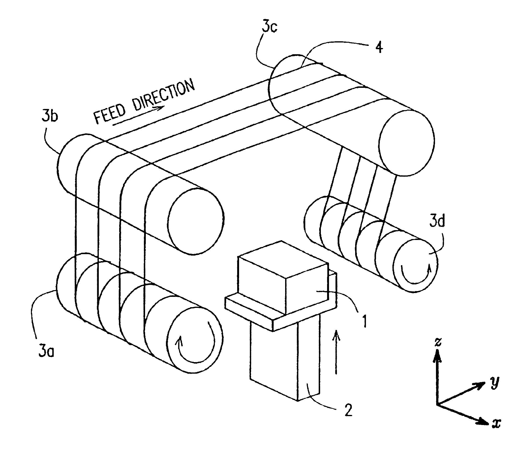
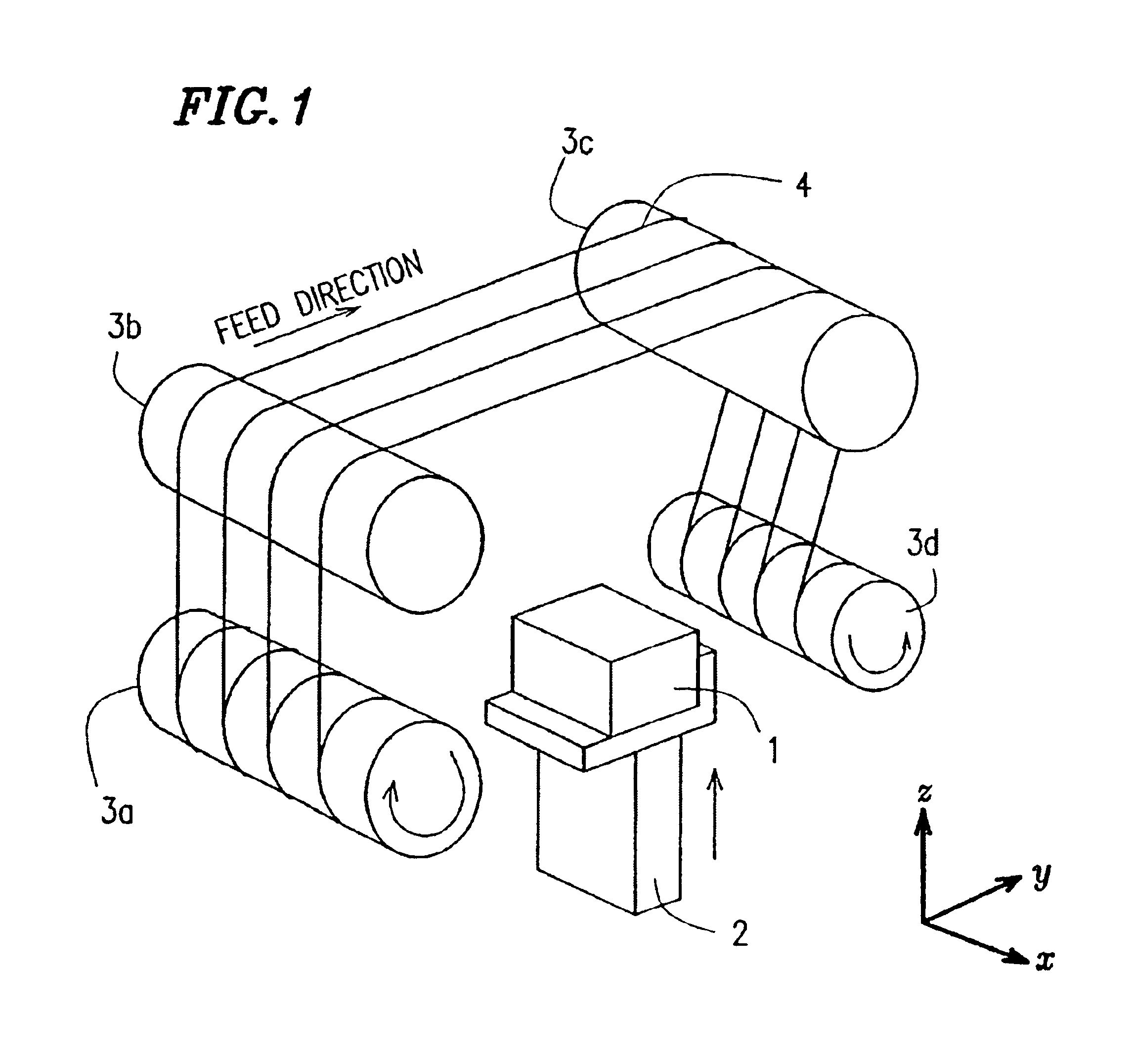
[0058]FIG. 1 illustrates an exemplary construction of a wire-saw machine according to Preferred Embodiment 1 of the present invention. The illustrated machine includes a drive device 2 supporting a green compact 1 to be machined for driving upward and downward (in the z-axis direction) and a plurality of rolls 3a, 3b, 3c and 3d.

[0059]A wire-saw 4, including a wire and abrasive grains fixed to the wire as described above, is wound in lines around the rolls 3a to 3d and travels in the direction that is substantially parallel to the y-axis. The lines of the wire-saw 4 are preferably arranged at substantially equal pitches in the x-axis direction, and the pitch of the arrangement (wire pitch) is arbitrarily determined depending on the size (thickness) of plates cut from the green compact 1 as a block. In a preferred embodiment of the present invention, the wire pitch is preferably about 1 mm to about 30 mm.

[0060]The outer diameter of the wire used for the wire-saw 4 is preferably in th...

embodiment 2

[0091]FIG. 9 illustrates an exemplary construction of a magnet powder compact production system 100 including a wire-saw machine 20 according to Preferred Embodiment 2 of the present invention.

[0092]The magnet powder compact production system 100 includes a compaction machine 10 and the wire-saw machine 20. The magnet powder compact production system 100 further includes a belt conveyor 16 for transporting green compacts 1 from the compaction machine 10 to the wire-saw machine 20, a belt conveyer 42 for transporting sliced compact pieces 1a from the wire-saw machine 20 to a sintering case 50, and a transfer machine 30 for transferring the green compacts 1 from the belt conveyor 16 to the wire-saw machine 20 and transferring the compact pieces 1a from the wire-saw machine 20 to the belt conveyer 42.

[0093]The magnet powder compact production system 100 is enclosed with a protection wall 70 to enable substitution of nitrogen gas for the air, for example, to decrease the oxygen concentr...

embodiment 3

[0115]FIG. 12 illustrates an exemplary construction of a wire-saw machine 40 suitably used for a method for manufacturing a sintered magnet according to Preferred Embodiment 3 of the present invention.

[0116]The wire-saw machine 40 shown in FIG. 12 is different from the wire-saw machine shown in FIG. 1 in that a lubricant applying device 5 is provided. Components having substantially the same functions as those of the wire-saw machine shown in FIG. 1 are denoted by the same reference numerals, and repetitive description thereof is omitted.

[0117]In the wire-saw machine 40, a cutting fluid 6 is applied to a wire-saw 4 by the lubricant applying device 5 before the wire-saw 4 comes into contact with a green compact 1 for cutting. The lubricant applying device 5 preferably includes a container 5a for retaining the cutting fluid 6 and a pan 5b for collecting the cutting fluid overflowing from the container 5a. The cutting fluid 6 is kept in the state of overflowing from the top opening of ...


PUM

PropertyMeasurementUnit
outer diameteraaaaaaaaaa
particle sizeaaaaaaaaaa
outer diameteraaaaaaaaaa

Abstract

A method for manufacturing a sintered magnet includes the steps of producing a green compact of powder for the sintered magnet, machining the green compact with a wire-saw, and sintering the green compact.

Description

TECHNICAL FIELD[0001]The present invention relates to a method for manufacturing a sintered magnet.BACKGROUND ART[0002]A rare earth sintered magnet is manufactured by pulverizing a rare earth magnetic alloy (material alloy) into alloy powder, compacting the alloy powder to obtain a green compact, sintering the green compact and subjecting the sintered body to an aging treatment, machining and other such processes. Currently, as rare earth sintered magnets, two types of magnets, rare earth-cobalt type magnets and rare earth-iron-boron type magnets, are used extensively in various fields of applications. Among others, rare earth-iron-boron type magnets (which will be referred to herein as “R—Fe—B type magnets” wherein R is at least one type of element selected from the group consisting of rare earth elements and yttrium, Fe is iron, and B is boron) are used more and more often in various types of electronic appliances because the R—Fe—B type magnets exhibit a magnetic energy product t...

Claims


Application Information

Patent Timeline
Patent Type & Authority Patents(United States)
IPC IPC(8): B22F3/00B23P13/04B26D1/44B22F5/00B28D5/00B28D5/04C04B35/515C04B35/58C22C1/04H01F1/057H01F41/02
CPCB22F5/003B28D5/007B28D5/0076B28D5/045C04B35/5156C04B35/5805C22C1/0441H01F1/0577H01F41/0253H01F41/0266Y10T29/49995B22F2998/10B22F3/02B22F3/10Y10T83/9292Y02P70/10
Inventor TANAKA, ATSUOMATSUGAMI, SHOICHIIWASAKI, TADAHIROOGAWA, ATSUSHIMORIMOTO, HITOSHI
Owner HITACHI METALS LTD
Why Eureka
Try Eureka