Apparatus for treating particles utilizing a flow control device

a flow control device and apparatus technology, applied in the direction of superimposed coating process, liquid/solution decomposition chemical coating, manufacturing tools, etc., can solve the problems of large space and energy required for system operation, high construction, maintenance and installation costs, and prone to failure, so as to achieve efficient treatment of a large amoun

Inactive Publication Date: 2007-08-23
SURFACE CHEMISTS OF FLORIDA
View PDF21 Cites 6 Cited by
  • Summary
  • Abstract
  • Description
  • Claims
  • Application Information

AI Technical Summary

Benefits of technology

[0009] Accordingly, the subject invention provides an apparatus and method for efficiently treating a large amount of particles with a minimal amount of coating and for ensuring that the particles maintain a predetermined flow rate and do not become clogged within the apparatus.

Problems solved by technology

These drum systems require large amounts of space and energy to operate.
Also, these systems can be expensive to construct, maintain and install.
Other prior art systems utilize other rotational parts for applying the coating, which can likewise be expensive and are also prone to failure.
The '903 patent, however, does not includes a mechanism for ensuring proper flow of particles and to reduce the likelihood of clogging the device.

Method used


Image

  • Apparatus for treating particles utilizing a flow control device
  • Apparatus for treating particles utilizing a flow control device
  • Apparatus for treating particles utilizing a flow control device

Examples


Embodiment Construction

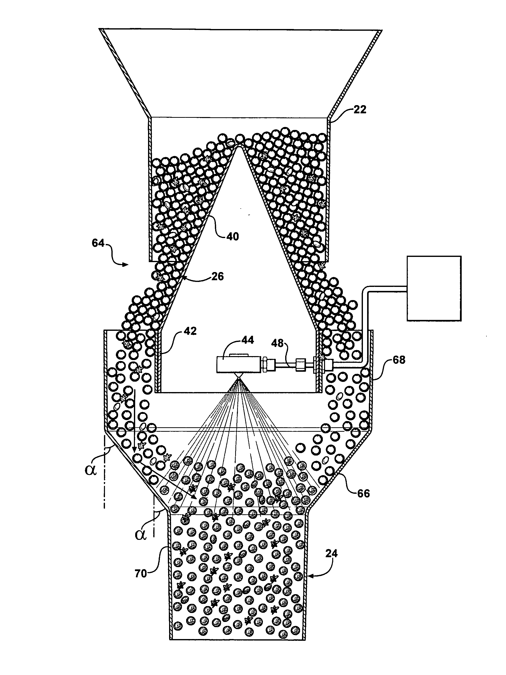
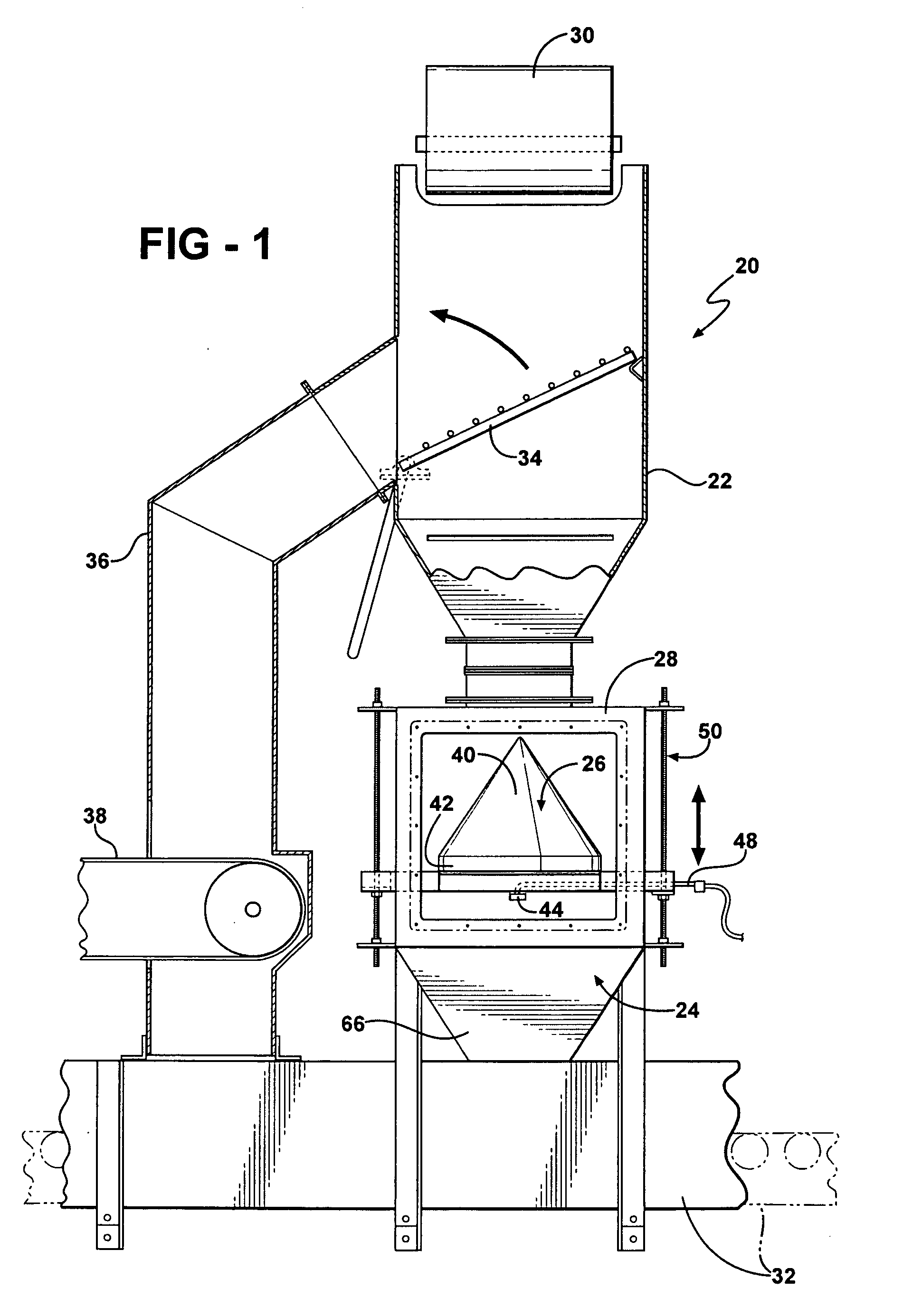
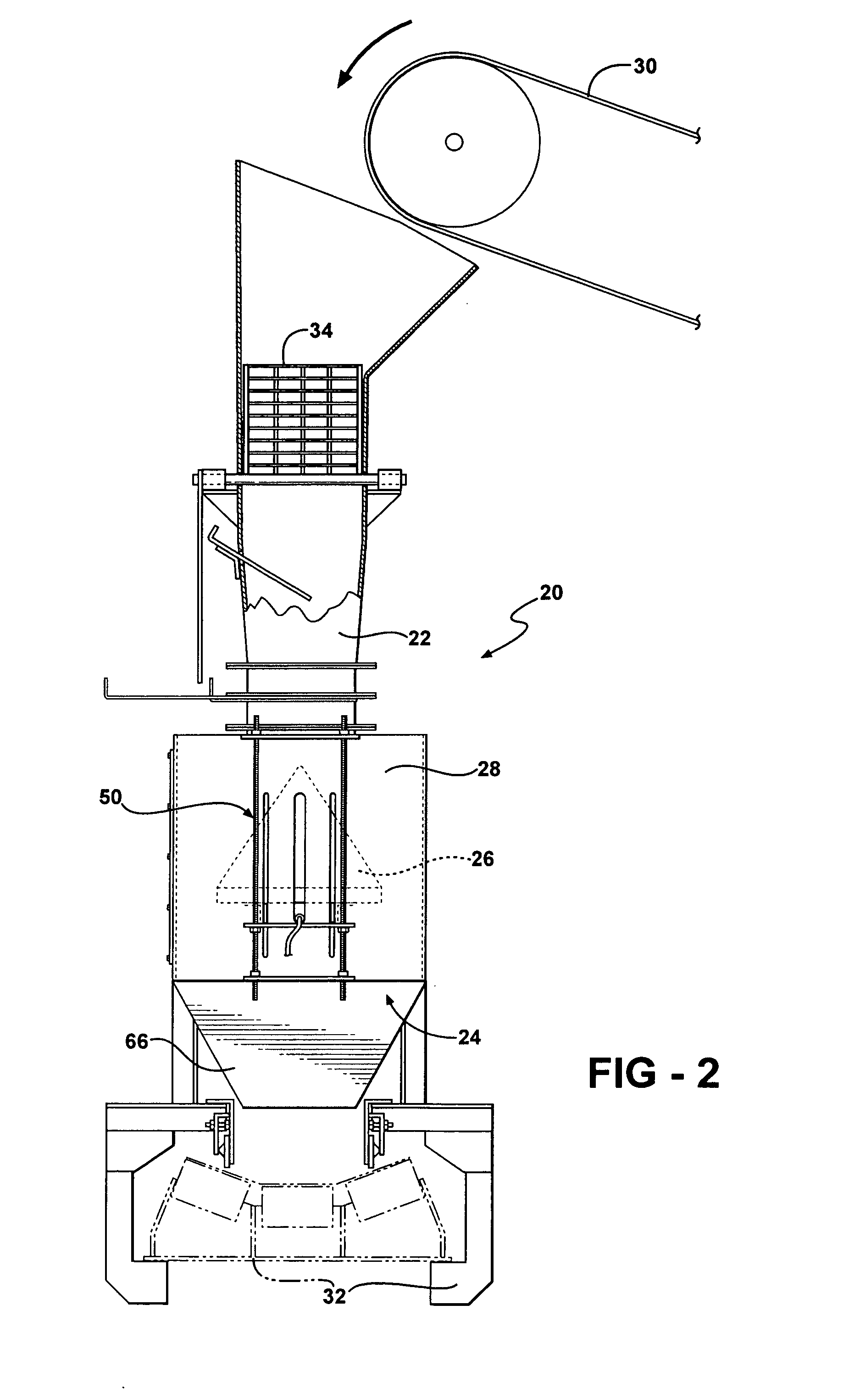
[0022] Referring to the Figures, wherein like numerals indicate like or corresponding parts throughout the several views, an apparatus in accordance with the subject invention is generally shown at 20 in FIGS. 1 and 2. The apparatus 20 includes a feed chute 22 and an exit chute 24. The feed chute 22 has an inlet for receiving particles and an outlet for discharging the particles (the particles are not shown in this Figure). The feed chute 22 is preferably configured as a hopper having angled walls at an inlet thereof. The exit chute 24 is discussed in greater detail below. A diffuser 26 is disposed between the feed 22 and exit 24 chutes. A feed conveyor 30 is preferably disposed over the feed chute 22 to provide a desired inflow of particles. An exit conveyor 32 is preferably disposed below the exit chute 24 to capture and transport treated particles as the particles are discharged from the apparatus 20. The feed chute 22, exit chute 24, and conveyors 30, 32 are know to those skille...


PUM

PropertyMeasurementUnit
sizeaaaaaaaaaa
flow rateaaaaaaaaaa
volumetric sizeaaaaaaaaaa

Abstract

An apparatus and method for treating a plurality of particles with a coating. The apparatus includes a feed chute and a diffuser having an angled wall to define a gap between the feed chute and the diffuser. An applicator sprays a coating for treating a plurality of particles and an exit chute captures the treated particles. A flow control device is provided for dynamically adjusting a size of the gap between the feed chute and the diffuser as the particles pass through the gap for ensuring a predetermined flow rate of the particles about the diffuser is maintained.

Description

BACKGROUND OF THE INVENTION [0001] 1. Field of the Invention [0002] The subject invention relates to an apparatus for treating particles and ensuring that the particles maintain a predetermined flow rate. [0003] 2. Description of Related Art [0004] The prior art is replete with various methods of applying coatings, typically in a liquid form, to solid particles. Many of these prior art systems use a horizontally rotational chamber or drum where a stream of a liquid coating is applied as the particles roll within the drum. Examples of these drum type systems are disclosed in U.S. Pat. Nos. 5,443,637 and 5,501,874. These drum systems require large amounts of space and energy to operate. Also, these systems can be expensive to construct, maintain and install. Other prior art systems utilize other rotational parts for applying the coating, which can likewise be expensive and are also prone to failure. For example, U.S. Pat. Nos. 4,596,206 and 2,862,511 utilize rotary applicators for app...

Claims


Application Information

Patent Timeline
Patent Type & Authority Applications(United States)
IPC IPC(8): B05D7/00B05D5/00B05C5/00
CPCB01J2/006B05D2258/00B05D1/02B05B13/025
Inventor NEVIN, JAMES E. IV
Owner SURFACE CHEMISTS OF FLORIDA
Why Eureka
Try Eureka