Orthodontic closed coil spring assembly and method of use thereof

a closed coil spring and assembly technology, applied in the field of orthodontic closed coil spring assemblies, can solve the problems of inability to fix the eyelet on either end of the closed coil spring into the head of an anchorage device, the eyelet used on either end is too large, and the procedure has proved difficult and time-consuming. achieve the effect of convenient looping

Inactive Publication Date: 2007-08-23
UNDER DOG MEDIA
View PDF8 Cites 19 Cited by
  • Summary
  • Abstract
  • Description
  • Claims
  • Application Information

AI Technical Summary

Benefits of technology

[0013]In another embodiment of the invention, each connecting plate is a flexible lasso directly connecting to the closed coil spring. The flexible lasso can be easily looped over an anchorage head regardless of the head shape or geometry and locked with the neck of the anchorage head when the pulling force from the closed coil spring is applied, thereby tightening the lasso around the head of the anchorage device.
[0014]Another aspect of utilizing the invention is a connecting plate in the form of a hairpin clip, which comprises a clip and two press tabs connected to the clip. The hairpin clip can be easily placed onto the neck of an anchorage head and remains in a locking position.
[0015]Another aspect of the present invention is directed to the connecting plate in the form of a flexible wire which can be placed easily around the neck of an anchorage head, and the springy wire can embrace and lock with the neck of the anchorage head with a force of the flexible wire.

Problems solved by technology

There exists a common problem with the application of the closed coil spring assembly.
In one example, the eyelet used on either end of the closed coil spring is too small to be fixed into the head of an anchorage device.
In another example, the eyelet used in either end is too large, such that the eyelet is easily dislodged from the head of an anchorage device after placement of the closed coil spring assembly.
However, such a procedure has proven difficult and time consuming.
However, placing a standard orthodontic O-ring over the eyelet and the head of an anchorage device is unhygienic and may provide a reservoir for food and debris to collect around the head of the anchorage device, thereby increasing the risk of infection of the anchorage device.
Moreover, placing the O-ring is time consuming and does not provide sufficient attachment in all circumstances.
In application of a closed coil spring assembly with a TAD, the same problem exists as described above, in that the eyelet of the closed coil spring assembly may be either too small or too large.

Method used


Image

  • Orthodontic closed coil spring assembly and method of use thereof
  • Orthodontic closed coil spring assembly and method of use thereof
  • Orthodontic closed coil spring assembly and method of use thereof

Examples


Embodiment Construction

[0029]While the making and using of various embodiments of the present invention are discussed in detail below, it should be appreciated that the present invention provides for inventive concepts capable of being embodied in a variety of specific contexts. The specific embodiments discussed herein are merely illustrative of specific manners in which to make and use the invention and are not to be interpreted as limiting the scope of the instant invention.

[0030]The claims and specification describe the invention presented and the terms that are employed in the claims draw their meaning from the use of such terms in the specification. The same terms employed in the prior art may be broader in meaning than specifically employed herein. Whenever there is a question between the broader definition of such terms used in the prior art and the more specific use of the terms herein, the more specific meaning is meant.

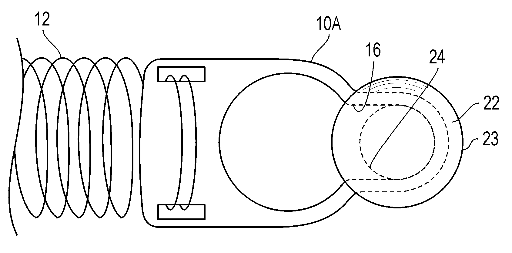
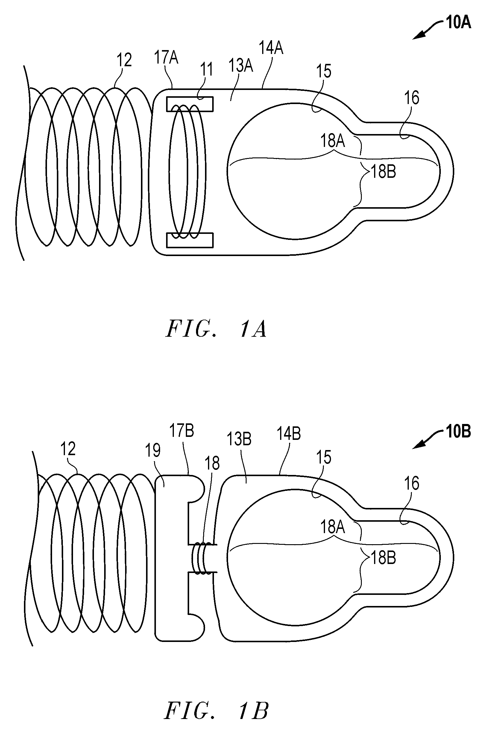
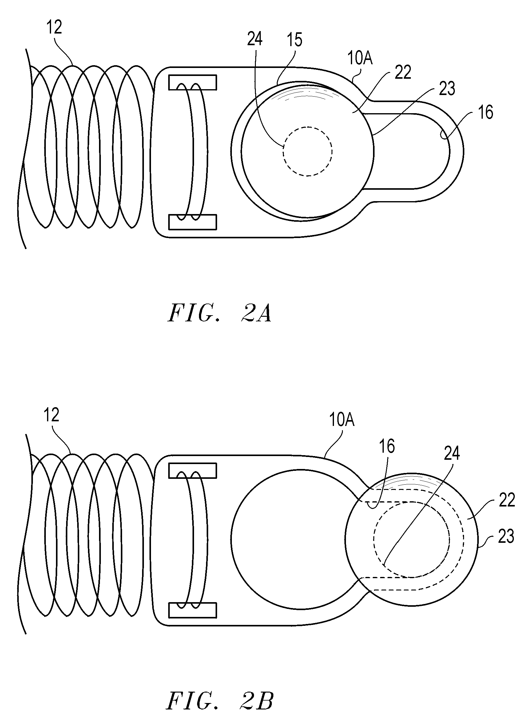
[0031]Referring now to FIG. 1A, an orthodontic closed coil spring assembly o...


PUM


Abstract

An orthodontic tensioning assembly, comprising a tensioner attachment body having a first end and a second end, wherein the first end of the tensioner attachment body has an opening adapted to removably receive a dental anchorage structure, and wherein the second end of the tensioner attachment body is adapted to removably couple a tensioning element.

Description

CROSS REFERENCE TO RELATED APPLICATION[0001]This application claims the benefit of U.S. Provisional Application Ser. No. 60 / 775,529, filed Feb. 22, 2006, entitled: ORTHODONTIC CLOSED COIL SPRING ASSEMBLY AND METHOD OF USE THEREOF by inventor Jason B. Cope [Attorney Docket No. 45128-P002V1].STATEMENT REGARDING FEDERALLY SPONSORED RESEARCH OR DEVELOPMENT[0002]Not applicable.THE NAMES OF THE PARTIES TO A JOINT RESEARCH AGREEMENT[0003]Not applicable.REFERENCES TO A “SEQUENCE LISTING”[0004]Not applicable.BACKGROUND OF THE INVENTION[0005]The present invention relates generally to orthodontic appliances and, more particularly, to orthodontic closed coil spring assemblies for providing durational corrective resistance forces for adjustment of a patient's teeth.[0006]In today's modern orthodontics, spring assemblies are used to assist the orthodontist with the re-alignment of a patient's teeth. One such spring assembly is a closed coil assembly. A closed coil spring assembly includes a close...

Claims


Application Information

Patent Timeline
Patent Type & Authority Applications(United States)
IPC IPC(8): A61C3/00
CPCA61C7/00A61C8/0096A61C7/22
Inventor COPE, JASON B.
Owner UNDER DOG MEDIA
Why Eureka
Try Eureka