Method for three-dimensional inventory link

a technology of three-dimensional inventory and linkage, applied in the field of data management, can solve the problems of difficult to locate the device responsible for the problem in the network operations center, the difficulty of locating the device in the row, the column, the aisle or the rack housing the device,

Inactive Publication Date: 2007-08-23
AMERICAN TELEPHONE & TELEGRAPH CO
View PDF30 Cites 16 Cited by
  • Summary
  • Abstract
  • Description
  • Claims
  • Application Information

AI Technical Summary

Benefits of technology

[0010] A method of locating a device associated with a network problem is presented. In one embodiment of the present invention, a three-dimensional image of a network operations center is presented. The three-dimensional image is presented in a graphical user interface (GUI). A network operator may operate the GUI. Operating the GUI causes a series of images to be displayed. The series of images create a virtual reality experience for the network operator. As such, the network operator may explore a network operations center by operating a GUI that displays a sequence of three-dimensional images depicting the network operations center. In addition, the three-dimensional images include alarm indication. For example, a red light may be displayed in a specific rack associated with an alarm. By operating a GUI (i.e., panning, zooming, etc.), a sequence of images are presented which give the network operator the experience of moving through the network operations center to the location of the device responsible for the alarm.

Problems solved by technology

With the size of modern networks, these network operations centers are typically very large.
In addition, because of the size and complexity of many networks, many distributed network operations centers are deployed.
Therefore, when there is a network problem, not only does the network operations center personnel have to identify the device, but also they are required to identify the impacted end users.
However, even after information is provided on a network problem, it is sometimes difficult to locate the device that is responsible for the problem in the network operations center.
For example, in large network operations centers, it may be difficult to locate the row, the column, the aisle, or the rack housing a device that is causing a network problem.
Further, it may be difficult to locate the additional users that will be affected by the network problem if you are unable to locate the specific device that is causing the network problem.
In conventional network operations centers, since the network operators are usually unable to locate the problem device in the network operations center, the network operators typically will call a series of customers that they think may be affected by the problem.
The inability to specifically locate the device in the network operations center which in turn results in wasted time contacting unaffected end users is an inefficient and an ineffective way of running a network operations center.

Method used


Image

  • Method for three-dimensional inventory link
  • Method for three-dimensional inventory link
  • Method for three-dimensional inventory link

Examples


Embodiment Construction

[0022] While the present invention is described herein with reference to illustrative embodiments for particular applications, it should be understood that the invention is not limited thereto. Those having ordinary skill in the art and access to the teachings provided herein will recognize additional modifications, applications, and embodiments within the scope thereof and additional fields in which the present invention would be of significant utility.

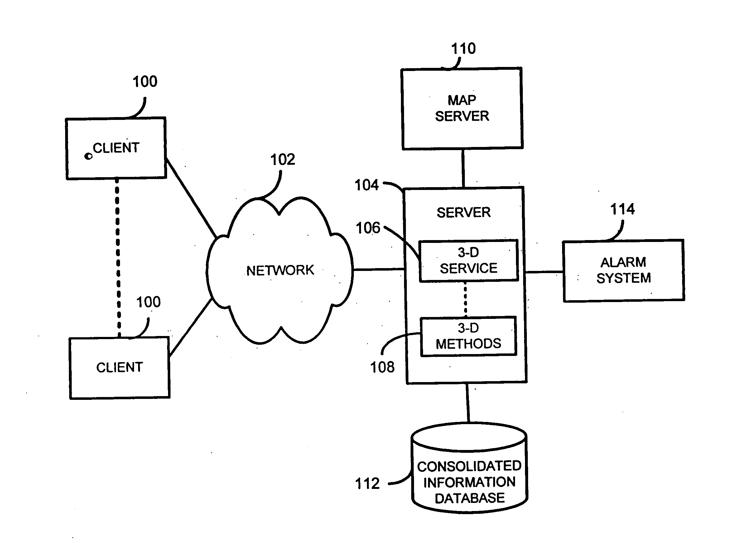
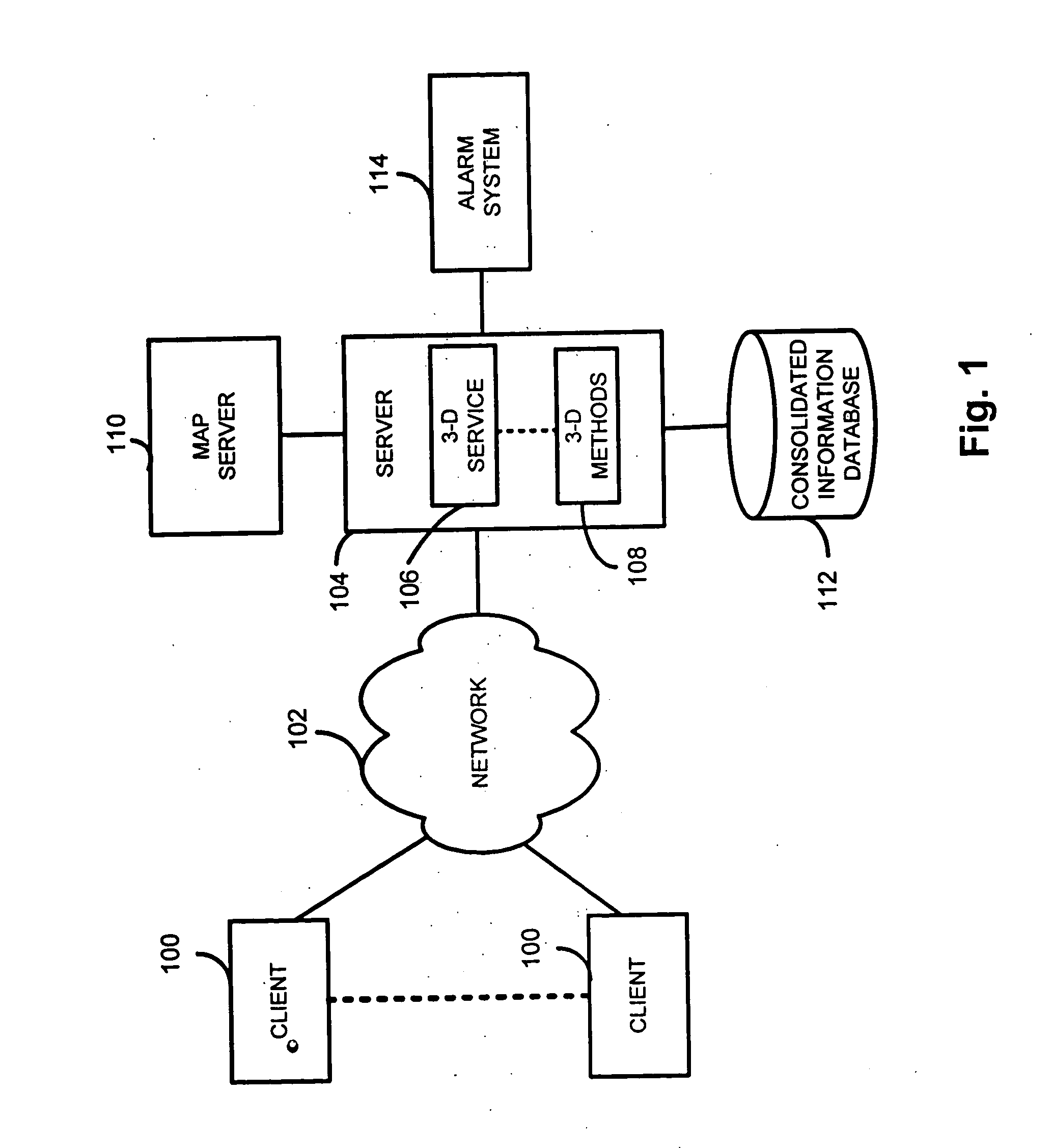
[0023] Three-dimensional images of a network operations center are presented to an end user. The three-dimensional images are presented in a GUI. As such, an end user connected to a network can operate the GUI and identify the location of a device responsible for a network problem. For example, in a web server environment, where hundreds of web servers are operating, an end user with a connection to the network may operate a GUI and determine the location of the specific web server that is responsible for a network problem. As such,...


PUM


Abstract

In accordance with the teachings of the present invention, a method is presented for providing an end user with a virtual reality experience. A server generates three-dimensional information. The three-dimensional information is generated using real-time alarm information representing an alarm, VRML schema information and meta-data. A client receives the three dimensional information. A three-dimensional image of a network operations center including a device responsible for the alarm is presented in a GUI. Operating the GUI allows the end user to experience moving through the operations center to the location of the device responsible for the alarm.

Description

CROSS REFERENCE TO RELATED APPLICATIONS [0001] This application is a continuation of provisional application Ser. No. 60 / 489,331 entitled “METHOD FOR THREE-DIMENSIONAL INVENTORY LINK” filed on Jul. 22, 2003, the contents of which are incorporated herein by reference.BACKGROUND OF THE INVENTION [0002] 1. Field of the Invention [0003] This invention relates to data management. Specifically, the present invention relates to data processing. [0004] 2. Background of the Invention [0005] A network operations center is often considered the heart of a network. The network operations center often includes hardware and software for monitoring the network. With the size of modern networks, these network operations centers are typically very large. Therefore, many rows of racks and devices may be resident in a modern network operations center. In addition, because of the size and complexity of many networks, many distributed network operations centers are deployed. Each of these centers typical...

Claims


Application Information

Patent Timeline
Patent Type & Authority Applications(United States)
IPC IPC(8): G06F15/173G06Q10/00
CPCG06Q10/087
Inventor ENGELMANN, JOHN STEVENESLAMBOLCHI, HOSSEINGADDAMANUGU, BALA SURYA SIVA SRIRANGAVITTAL, PRAKASHSTEWART, HAROLD JEFFREYBRITTAIN, ERIC AUDWOYNE
Owner AMERICAN TELEPHONE & TELEGRAPH CO
Why Eureka
Try Eureka