Systems and methods for tracking signal strength in wireless networks

a wireless network and signal strength technology, applied in the field of wireless network signal strength tracking systems and methods, can solve the problems of undesired compromise of the effective range of rf signals, undesired attenuation or interference of cellular rf signals, and weak cellular reception

Inactive Publication Date: 2010-11-02
VERIZON PATENT & LICENSING INC
View PDF15 Cites 50 Cited by
  • Summary
  • Abstract
  • Description
  • Claims
  • Application Information

AI Technical Summary

Problems solved by technology

For example, the effective range of RF signals may be undesirably compromised by geographic features such as mountains, canyons, buildings, and weather conditions.
Consequently, cellular reception may be weak, or even nonexistent, at some locations (e.g., in a basement of a building) within a cellular network.
Moreover, many other circumstances may undesirably attenuate or interfere with cellular RF signals.
For example, other radio signals or radiation produced by other sources may interfere with cellular signals.
Because numerous possible static and dynamic factors may affect RF signals as they travel through a cellular network, it is extremely difficult for network designers to predict the strength of the RF signals at every location within the cellular network.
As a result, cellular customers often experience “dead spots” within cellular networks.
Dead spots may cause cellular callers to experience interrupted telephone connections, unclear or unintelligible telephone conversations, and failures to establish connections.
These experiences may lead the carrier of a cellular network to lose both business and goodwill among customers.
This approach tends to be less than effective because customers may not travel to all locations within a network.
Moreover, customers may be either unable to identify the precise location at which a dead spot was experienced or not motivated to go to the trouble of reporting the dead spot.
Other conventional approaches for locating dead spots are labor intensive, time consuming, and not always accurate.
Not only is the specialized equipment costly, manual sampling of signal strength requires vast amounts of manpower to cover a dynamically changing grid of cellular signals.
Moreover, it may be extremely difficult, if not impossible, for employees to sample signal strength from every possible location within a cellular network.
However, none of the existing approaches for locating cellular telephones within a cellular network has been used for tracking, analyzing, and managing signal strength within a cellular network (e.g., in locating and correcting dead spots).
In sum, existing approaches for tracking signal strength in wireless network are time-consuming, labor-intensive, costly, and less than effective for precisely identifying all dead spots in wireless communication networks.
Consequently, wireless carriers often experience frustration in trying to track and eliminate dead spots.
Moreover, because existing approaches are less than effective, carriers often suffer losses of business and goodwill due to subscribers experiencing the inconvenience and frustration typically associated with the undesirable effects caused by dead spots in wireless networks.

Method used


Image

  • Systems and methods for tracking signal strength in wireless networks
  • Systems and methods for tracking signal strength in wireless networks
  • Systems and methods for tracking signal strength in wireless networks

Examples


Embodiment Construction

I. Overview

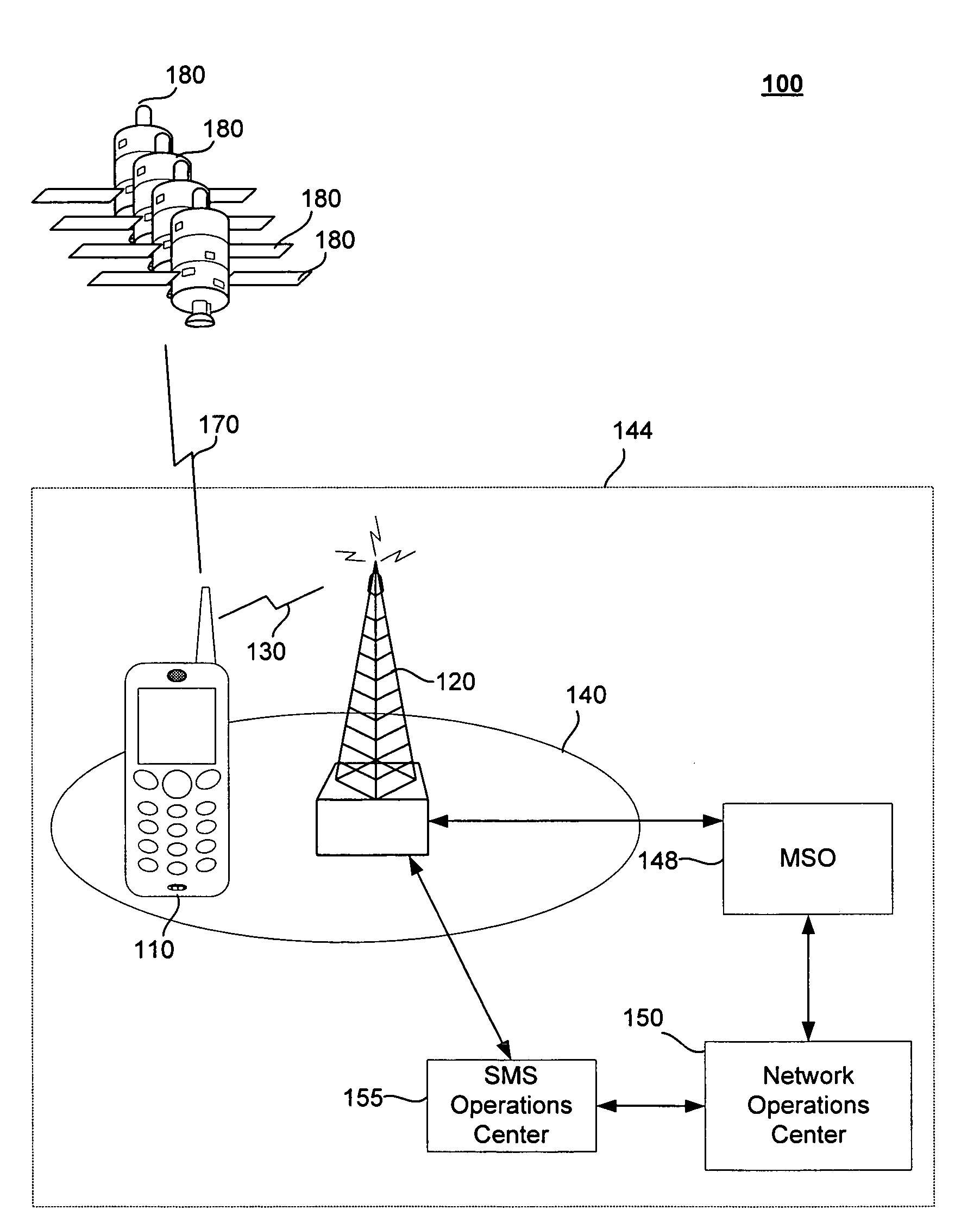
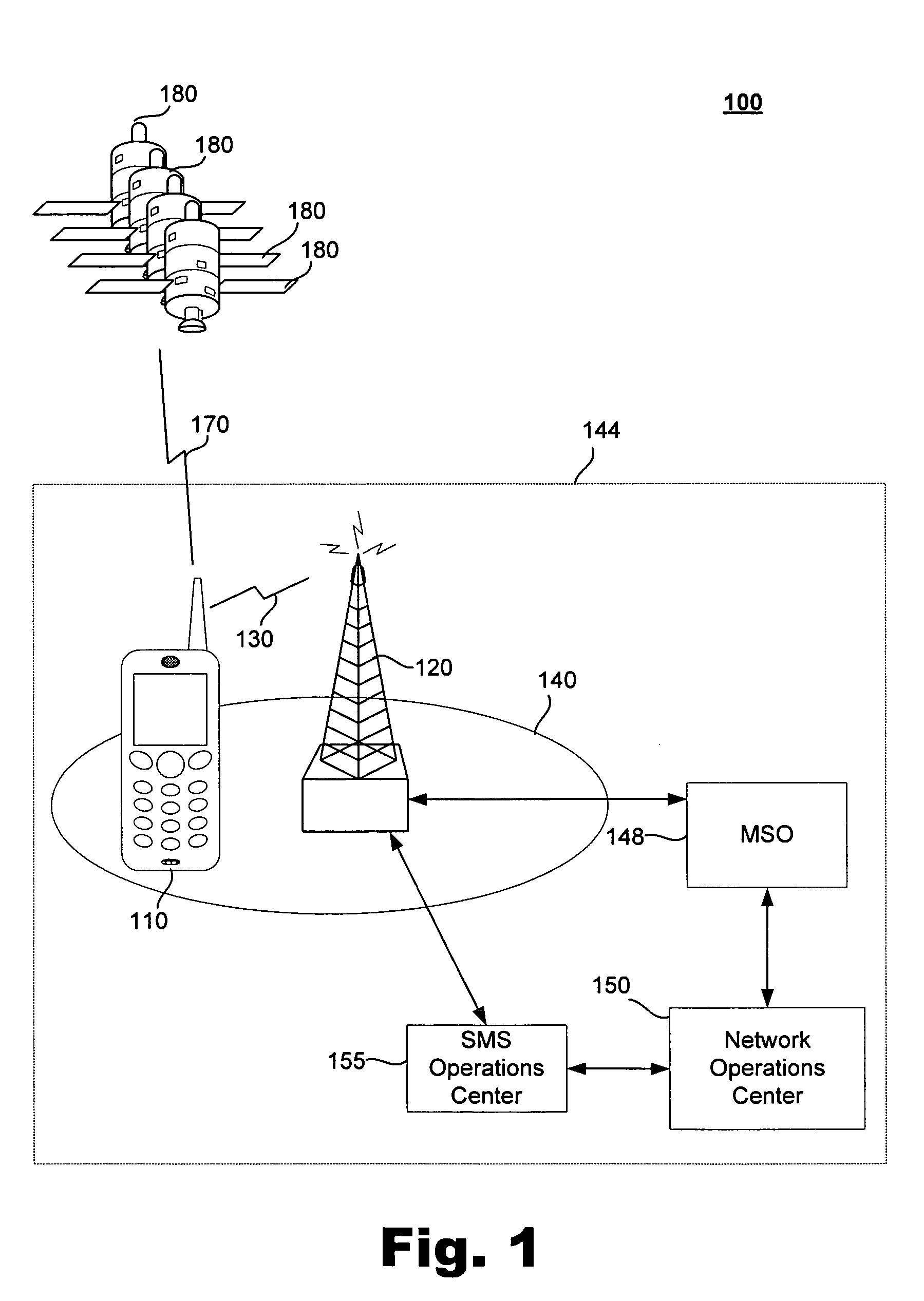
[0015]Preferred embodiments according to the present invention may be implemented as systems and methods for tracking downstream wireless signal strengths in wireless networks. More specifically, the described systems and methods (collectively the “system”) provide for the use of parameter data (e.g., location data, time data) to track signal strength within wireless networks. At least one positioning technology (e.g., GPS technology) other than wireless network positioning technologies (e.g., cellular network trilateration techniques) may be used to identify parameters (e.g., location, time, and / or velocity) of wireless devices configured to operate in the wireless network.

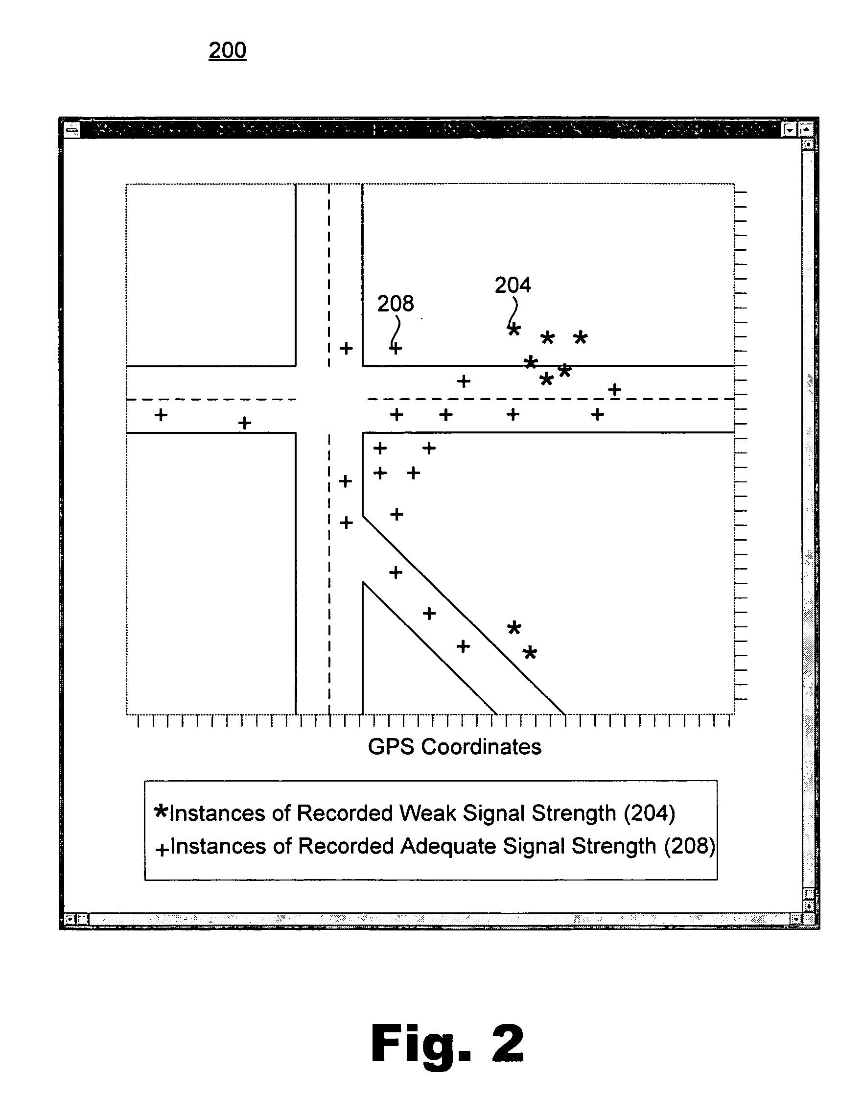
[0016]Wireless devices (e.g., cellular telephones) within a wireless network may be configured to measure the strength of received wireless network signals transmitted from wireless access points (e.g., base stations) used in the network. For certain measured signal strengths, corresponding parameter d...


PUM


Abstract

Tracking of signal strength in wireless networks is disclosed. In one of many possible embodiments, signal strength of a wireless signal received by at least one wireless device is measured, the wireless device being configured for operation in the wireless network. A parameter of the wireless device is determined, the parameter corresponding with the measurement of signal strength. The measured signal strength and the determined parameter are transmitted to a network operations center. The measured signal strength and the determined parameter are used to analyze signal coverage of the wireless network.

Description

BACKGROUND INFORMATION[0001]Wireless networks typically include signal transmitting antennae geographically positioned in a manner designed to provide contiguous signal coverage over a geographic service area. For example, cellular networks are generally organized into cells, with each cell having at least one antenna capable of transmitting radio frequency (“RF”) signals over a particular section of the service area. The cells of the network are positioned to provide cellular coverage over the geographic service area, such as the territory occupied by a city.[0002]Each cell is assigned a particular range of radio frequencies within a predetermined cellular band. Because an antenna of a cellular network transmits at relatively low power, the radio frequencies transmitted by the antenna are for the most part restricted to its corresponding cell. This allows the limited number of frequencies within a cellular band to be reused by different cells within a cellular network. As a result,...

Claims


Application Information

Patent Timeline
Patent Type & Authority Patents(United States)
IPC IPC(8): H04W24/00
CPCH04W24/06H04W24/10
Inventor SYLVESTER, JAMES E.
Owner VERIZON PATENT & LICENSING INC
Why Eureka
Try Eureka