Compression molded footwear and methods of manufacture

a compression molding and footwear technology, applied in the field of footwear articles, can solve the problems of shutting down an entire production line of footwear, increasing the overall manufacturing cost, and affecting the quality of footwear,

Inactive Publication Date: 2007-08-30
THE TIMBERLAND COMPANY
View PDF49 Cites 211 Cited by
  • Summary
  • Abstract
  • Description
  • Claims
  • Application Information

AI Technical Summary

Benefits of technology

[0019] In a preferred embodiment the first foam layer, second foam layer and middle layer are integrally formed by compression molding. Additionally, the step of integrally forming may include adhesively affixing the middle layer between the first foam layer and the second foam layer. The adhesive used in the step of integrally forming

Problems solved by technology

Such a method requires a large number of steps, each requiring a skilled person for completion thereof.
This increases the overall manufacturing cost and can lead to throughput problems arising from bottlenecks in one step of the process.
For example, the absence of the person responsible for one step in the process can shut down an entire production line of footwear.
Furthermore, the use of such complicated individual pieces leads to a product that is more difficult to design, requiring the design of both the individual pieces and how the pieces will fit together to form the shape of the shoe upper.
This further contributes to increased costs of the finished product, and increases lead time when designing the shoe.
However, the injection molding method presents significant additional problems.
Specifically, the complicated molds necessary to form the 3-D shape of a shoe upper increase costs and lead time due to the time required to manufacture these molds.
If not controlled, creep can result in continued expansion of the polymer.
This causes the shoe upper to stretch, which affects the fit quality of the shoe.
Additionally, because the majority of the shoe upper is formed in a single process step, there are no available intermediate steps that can control factory defects in the upper of the shoe.
Such defects typically arise due to the difficulty in controlling the expansion of foam after injection into the mold, particularly during cooling.
In order to control such defects, tolerances within the molds need to be widened, which can lead to overall fit problems with the finished product.
However, this method does not alleviate the expense required by complex 3-D molds or the increas

Method used


Image

  • Compression molded footwear and methods of manufacture
  • Compression molded footwear and methods of manufacture
  • Compression molded footwear and methods of manufacture

Examples


Embodiment Construction

[0035] In describing the preferred embodiments of the subject matter illustrated and to be described with respect to drawings, specific terminology will be employed for the sake of clarity. However, the invention is not intended to be limited to the specific terms so selected, and it is to be understood that each specific term includes all technical equivalents which operate in a similar manner to accomplish a similar purpose.

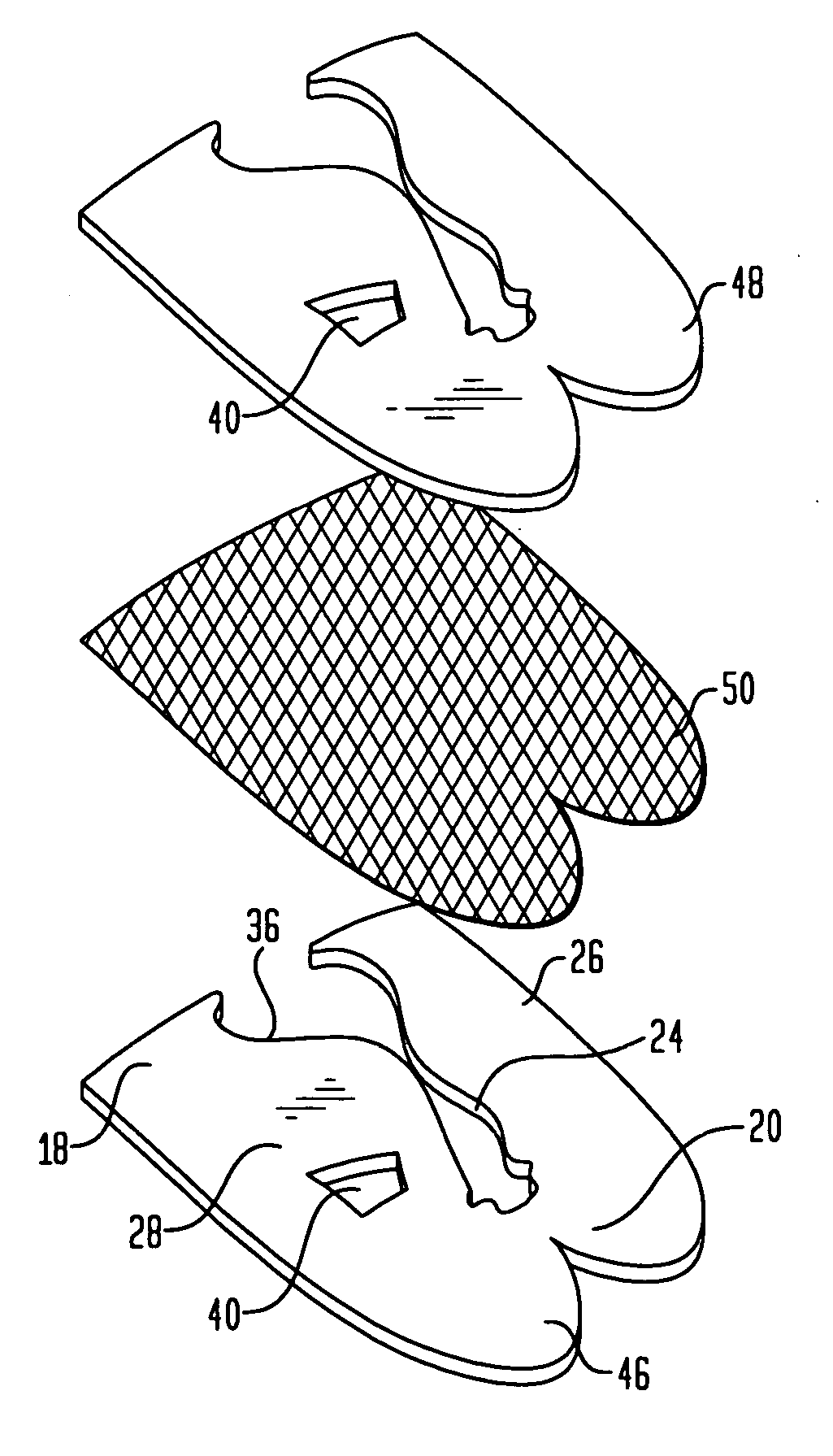
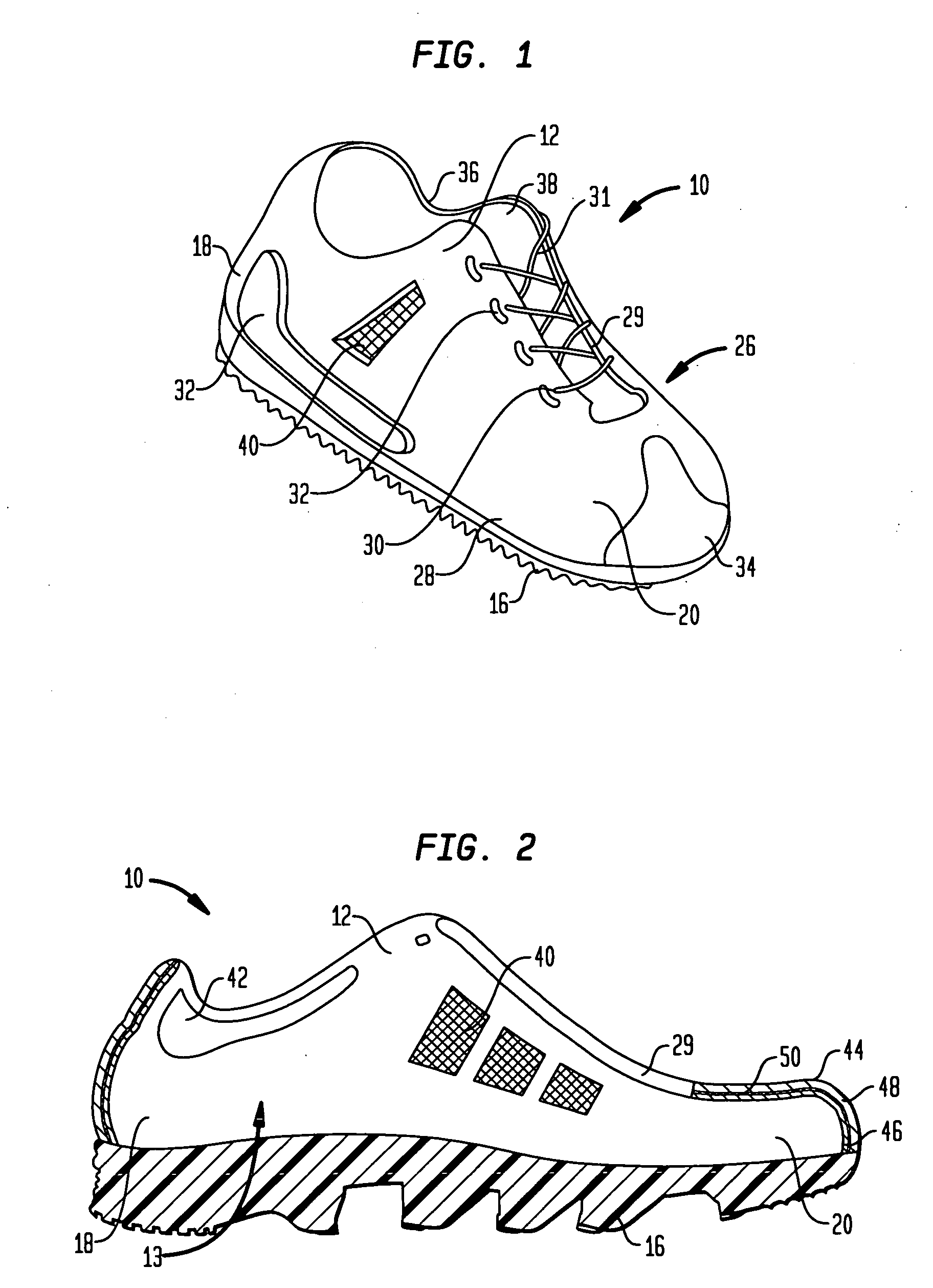
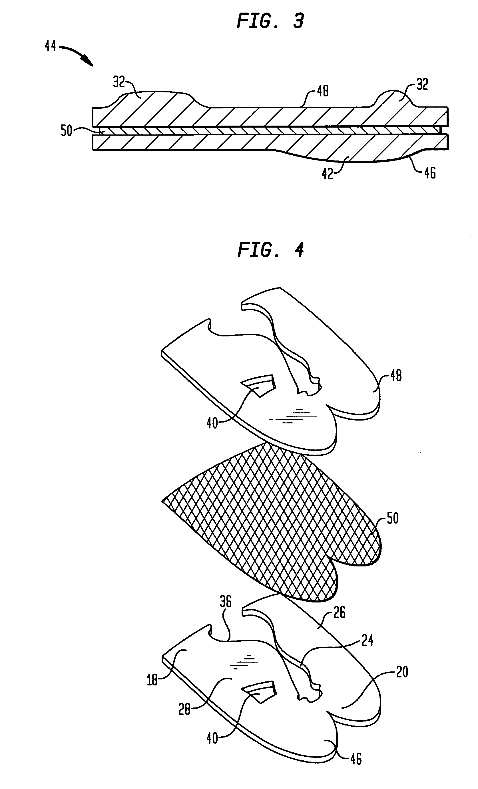
[0036] Referring to the drawings, wherein like reference numerals represent like elements, there is shown in FIG. 1, in accordance with one embodiment of the present invention, a shoe designated generally by reference numeral 10. Shoe 10 is generally constructed of an upper 12, an insole 14 (see FIG. 8), and an outsole 16. Upper 12 is designed to receive the foot of a wearer by defining a portion of foot receiving cavity 13 therein. The bottom portion of foot receiving cavity 13 is defined by insole 14, which is generally structured to support the foot of the ...


PUM

PropertyMeasurementUnit
Shapeaaaaaaaaaa
Thermoplasticityaaaaaaaaaa
Tensile strengthaaaaaaaaaa

Abstract

An article of footwear having an upper, which includes a first foam layer having a first surface and a second surface remote from the first surface, a second foam layer having a first surface and a second surface remote from the first surface, and a middle layer having a first surface and a second surface remote from the first surface. The first surface of the middle layer is affixed to the second surface of the first foam layer, and the second surface of the middle layer is affixed to the first surface of the second foam layer. The upper defines at least a portion of a foot receiving cavity for the article of footwear.

Description

BACKGROUND OF THE INVENTION [0001] The present invention relates generally to articles of footwear and, more particularly, to articles of footwear having multilayer molded uppers. [0002] Typically, many types of footwear are made by what is known as a cut and sew method, in which individual pieces of material are cut out and sewn together to form the three dimensional (“3-D”) shape of a footwear upper. In such a process, individual pieces of material are cut out according to a pattern, in which individual pieces are designated to form specified portions of the shoe upper. When the pieces are cut out, they are typically marked according to the portion of the upper which they are intended to form. The individual pieces are bonded, stitched and then lasted, giving the shoe the necessary 3-D shape. Other portions of the shoe may then be attached to the upper, such as an outsole, midsole, footbed, etc. [0003] Such a method requires a large number of steps, each requiring a skilled person...

Claims


Application Information

Patent Timeline
IPC IPC(8): A43B23/00B29D35/14
CPCA43B13/12B32B2437/02B29D35/146B32B5/32A43B23/022A43B23/0235A43B23/0255A43B23/042B32B5/18B32B5/245B32B7/12B32B25/00B32B25/045B32B1/00B32B2255/102B32B2266/0207B32B2266/0214B32B2266/0221B32B2266/0264B32B2266/06B32B2307/54B32B2307/724B32B2307/738B29D35/142A43B7/085
Inventor VATTES, DAVID L.DILLON, PETER
Owner THE TIMBERLAND COMPANY
Why Eureka
Try Eureka