Adjustable rear pistol sight

a rear sight and pistol sight technology, applied in the field of adjustable rear sight for pistols, can solve the problems of many adjustment options, unfavorable fine adjustment, and inability to adjust, and achieve the effect of dependable operation and rapid sight alignmen

Inactive Publication Date: 2007-08-30
KENGS FIREARMS SPECIALTY
View PDF7 Cites 36 Cited by
  • Summary
  • Abstract
  • Description
  • Claims
  • Application Information

AI Technical Summary

Benefits of technology

[0018] The sight has a laterally movable longitudinal sight notch, in accordance with standard adjustable sight practice. The sight is adjustable, by the use of an elevation adjustment screw, situated on one lateral side of the sight, and by the use of a horizontal or windage adjustment screw situated on the other lateral side of the sight. Both conspicuously identify the adjustment functions of the hinged and laterally movable sight notch defining sight block and permit adjustment in elevation without requiring the shooter to file the front sight blade. Windage adjustments are also accomplished without requiring the shooter to use a drift punch on the sight body.
[0019] The sight assembly's sight base and sight block upper surface are defined on the left and right by radiused corners terminating in substantially vertical left and right side walls of the sight base. The rear surface of the sight base is angled or contoured forwardly from vertical, toward the pistol muzzle, and when viewed from the rear as during aiming, the sight base has a square-shaped recess machined into the angled rear surface to leave a substantially vertical recessed wall disposed symmetrically around and framing the longitudinal sight notch. The rear recess in the sight base is machined by a tool moving in a vertical square-shaped pattern lying in a plane that is parallel to the center axis of the dovetail and transverse to the sight's longitudinal axis, leaving the thickness of the resulting rear recess larger nearer the bottom of the sight base, and tapering to virtually no recess thickness nearer the top of the sight base. The sight base's upper surface tapers downwardly from rear to front terminating at the front edge in a front angled wall having the same angle as the front wall of the dovetail that is carried on the bottom of the sight base. The upper surface of the sight base also includes the bowl-shaped recess or channel which is disposed symmetrically about the sight assembly's longitudinal axis, to leave an open interior to support and protect the hinged and laterally movable sight block between vertical side walls. A set screw is partially concealed beneath the hinged and laterally movable sight block and is disposed in a threaded through-hole in the sight base and extending generally transversely to the longitudinal axis, through the dovetail of the sight base. This set screw is intended to be tightened by a user and to bear against the dovetail notch planar lower surface in the pistol slide. The sight notch runs longitudinally from a vertical rear wall of the hinged and laterally movable sight block to a front facing vertical wall defined in the hinged and laterally movable sight block. The recessed vertical rear wall of the sight base provides a large expanse of shadow or reflection-free background to aid in rapid sight alignment.
[0020] When mounted on a pistol slide, the sight assembly, in accordance with the present invention, provides a substantially smooth structure affixed in the pistol dovetail with windage and elevation adjustment screws for changing the position of the hinged and laterally movable sight notch formed in the sight block. The sight also features the vertical planar rear recessed wall machined into the rear of the sight base to frame the sight notch. As discussed above, the side walls of the sight base are radiused and rounded to essentially eliminate any possibility of the sight assembly of the present invention providing a snagging hazard.
[0021] The adjustable rear pistol sight in accordance with the present invention provides a windage and elevation sight assembly that is durable, smooth, dependable in operation and that has no exposed parts or non-flush elements which would form a snagging hazard. It is a substantial advance in the art.

Problems solved by technology

Even a momentary delay in the smooth transition of the pistol from a carry position to a use position can have fatal consequences.
While the combat sights of the prior art do provide a somewhat smooth and snag-free draw, a clear sight picture and rugged service, they do not provide the adjustability many have come to enjoy when using target pistols equipped with adjustable target sights.
Adjustments for windage have previously often required the shooter to strike the side of the sight with a pin punch and hammer, to thereby force the sight laterally in the notch, a clumsy and inherently inaccurate procedure that is clearly not well suited to making fine adjustments.

Method used


Image

  • Adjustable rear pistol sight
  • Adjustable rear pistol sight
  • Adjustable rear pistol sight

Examples


Embodiment Construction

[0022] A full and complete understanding of the adjustable rear pistol sight, in accordance with the present invention, will be had by referring to the detailed description of the preferred invention, as set forth subsequently, and as seen in the accompanying drawings, in which:

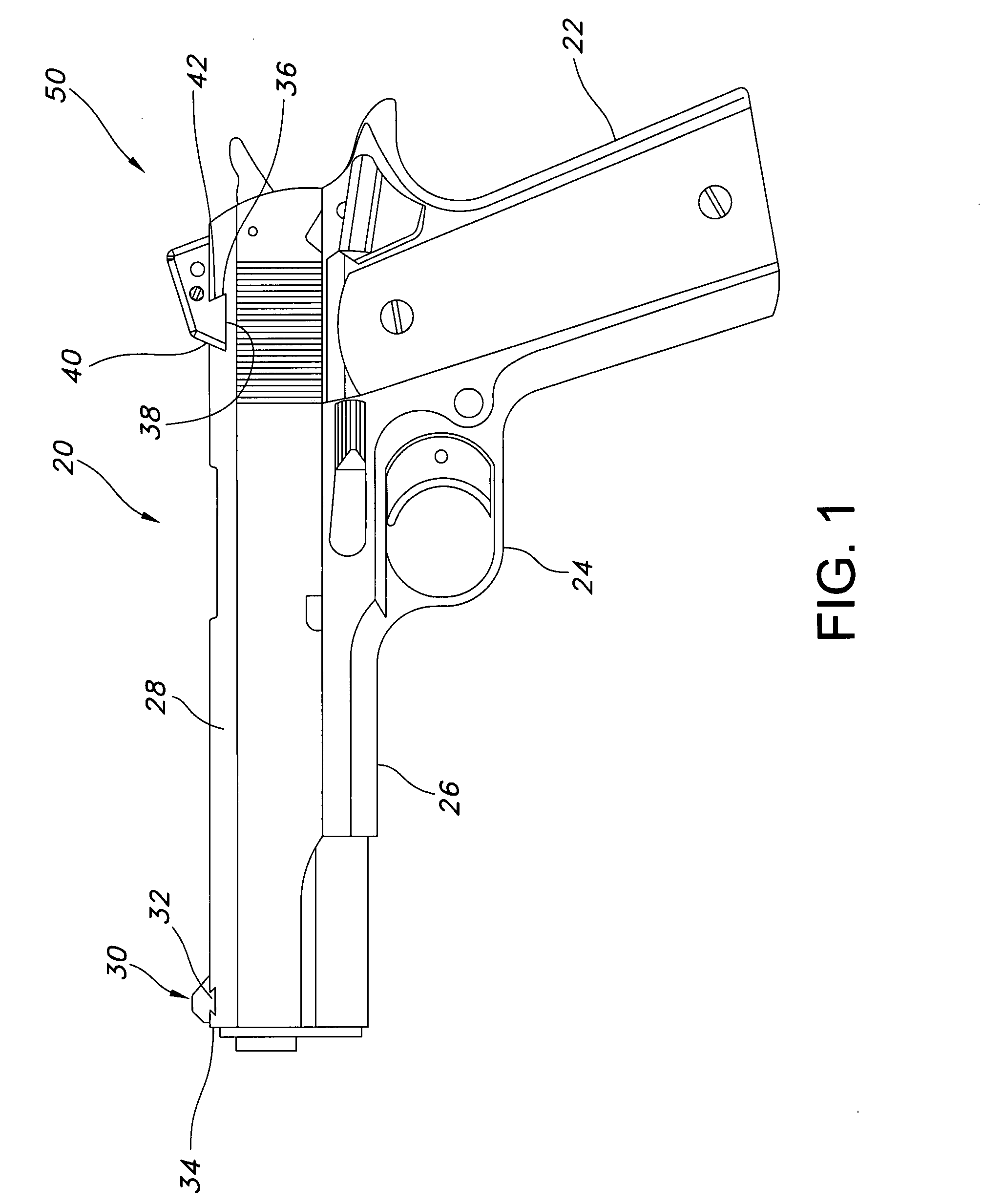
[0023]FIG. 1 is a schematic side elevation view of a pistol on which the adjustable rear sight of the present invention is mounted;

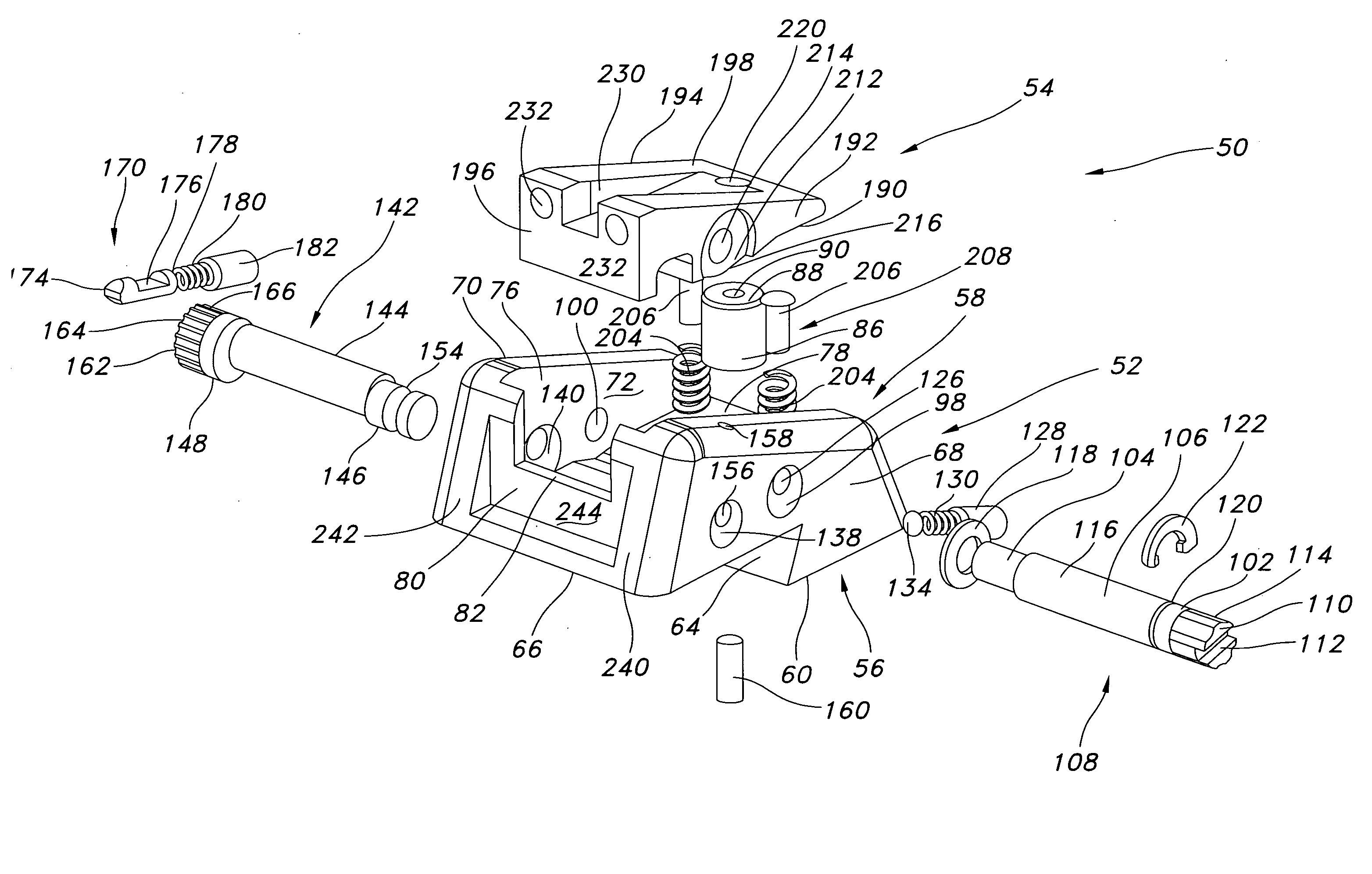
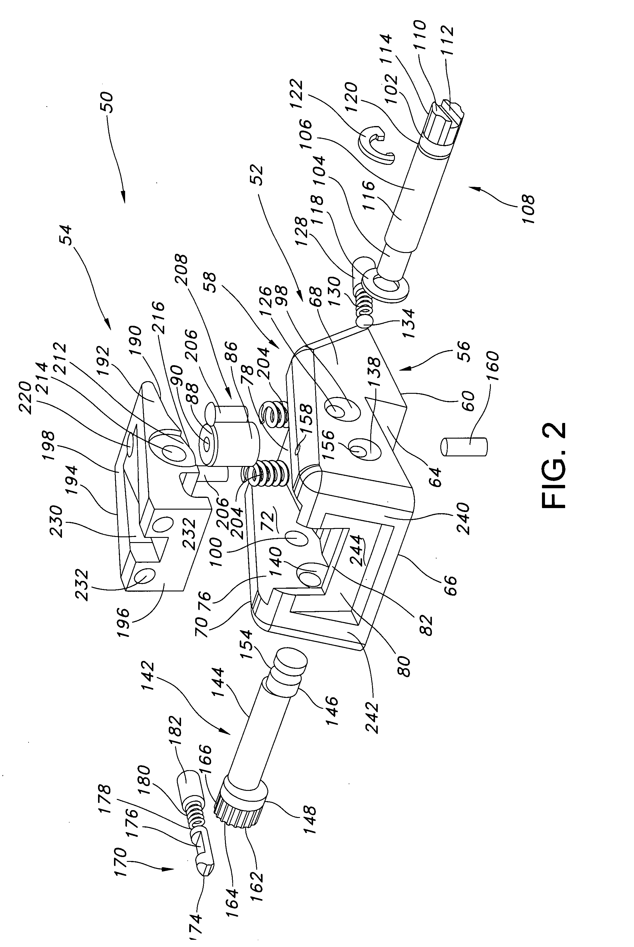
[0024]FIG. 2 is an exploded perspective view of the adjustable rear pistol sight of the present invention;

[0025]FIG. 3 is a top plan view of the adjustable rear pistol sight;

[0026]FIG. 4 is a side elevation view, in section, of the adjustable sight and taken along line IV-IV of FIG. 3;

[0027]FIG. 5 is a side elevation view, partly in section, of the adjustable sight and taken along line V-V of FIG. 3;

[0028]FIG. 6 is a side elevation view, in section, of the adjustable sight taken along line VI-VI of FIG. 3;

[0029]FIG. 7 is a side elevation view of the adjustable sight of FIGS...


PUM


Abstract

An adjustable rear pistol sight has a sight base and a sight block. The sight block is secured in a recess in the sight base and has both windage and elevation adjustment capabilities. The sight base has a dovetail that will be receivable in a cooperatively shaped notch in a slide of a pistol with which the adjustable rear sight is intended for use. The sight has no sharp edges or surfaces and is essentially snag-free.

Description

CROSS-REFERENCE TO RELATED APPLICATIONS [0001] This U.S. utility patent application claims priority, under 35 USC 119(e) and 120, to U.S. provisional patent application No. 60 / 750,051, filed Dec. 14, 2005. The disclosures of that application are expressly incorporated herein by reference.FIELD OF THE INVENTION [0002] The present invention is directed generally to an adjustable rear sight for a pistol. More specifically, the subject invention is directed to an adjustable rear pistol sight that is adjustable for both windage and elevation. Most specifically, the subject invention is directed to a windage and elevation adjustable rear pistol sight that is smooth, durable and compact in overall configuration and which is operable in a snag-free manner. The adjustable rear pistol sight includes a sight base and a sight block. The sight block is adjustable for windage and elevation through the provision of adjustment screws. There are no projecting portions of the screws, block or base. A...

Claims


Application Information

Patent Timeline
Patent Type & Authority Applications(United States)
IPC IPC(8): F41G1/00
CPCF41G1/26F41G1/10
Inventor ERTL, THOMAS
Owner KENGS FIREARMS SPECIALTY
Why Eureka
Try Eureka