Security Device Formed By Printing With Special Effect Inks

US20070200002A1Active Publication Date: 2007-08-30VIAVI SOLUTIONS INC

Image

  • Security Device Formed By Printing With Special Effect Inks
  • Security Device Formed By Printing With Special Effect Inks
  • Security Device Formed By Printing With Special Effect Inks

Examples


Embodiment Construction

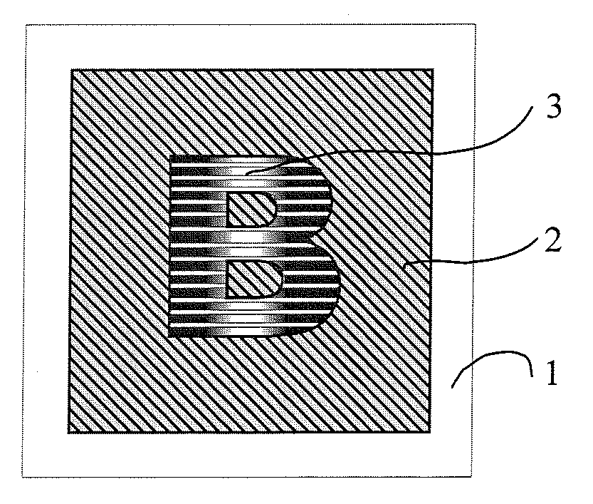
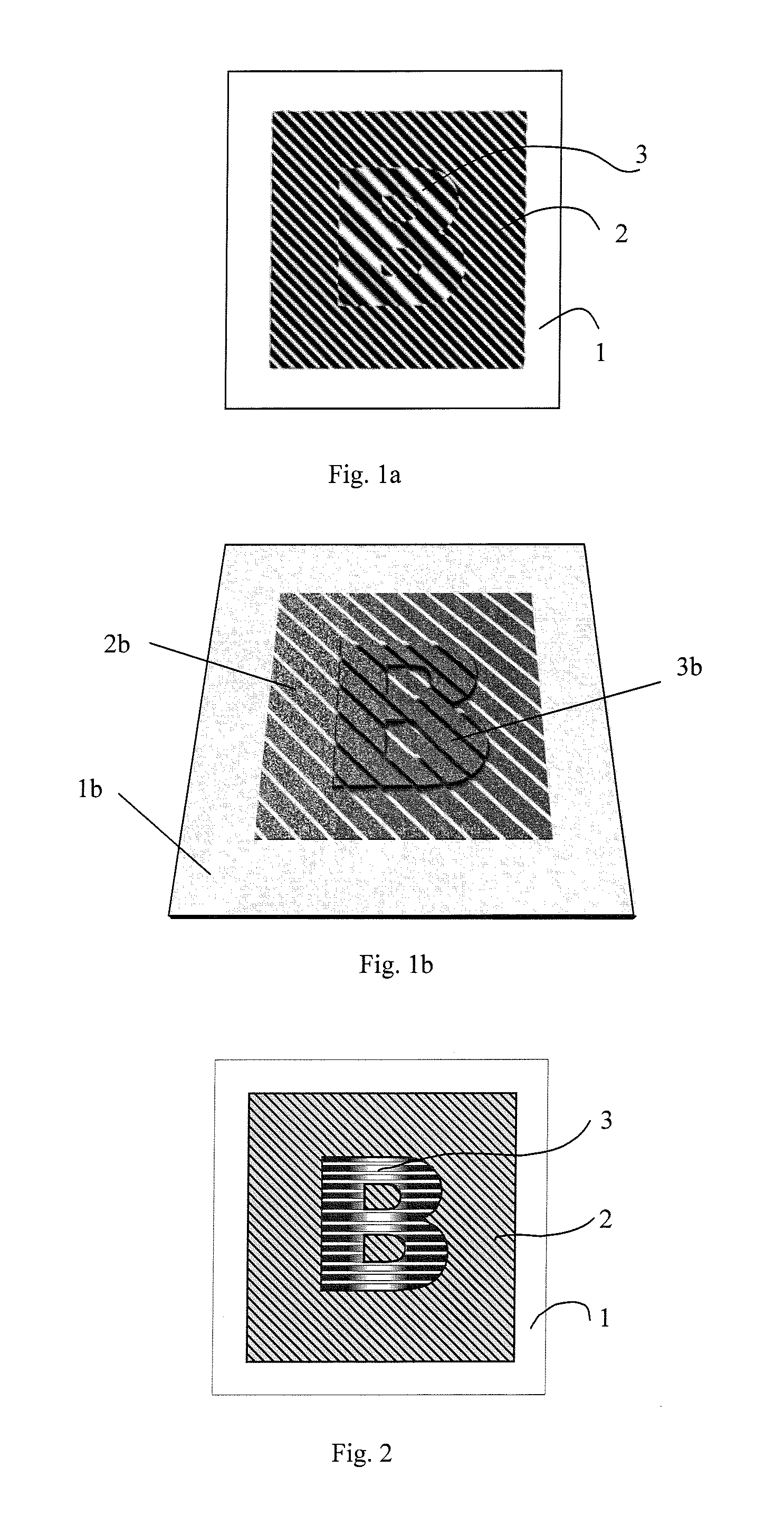
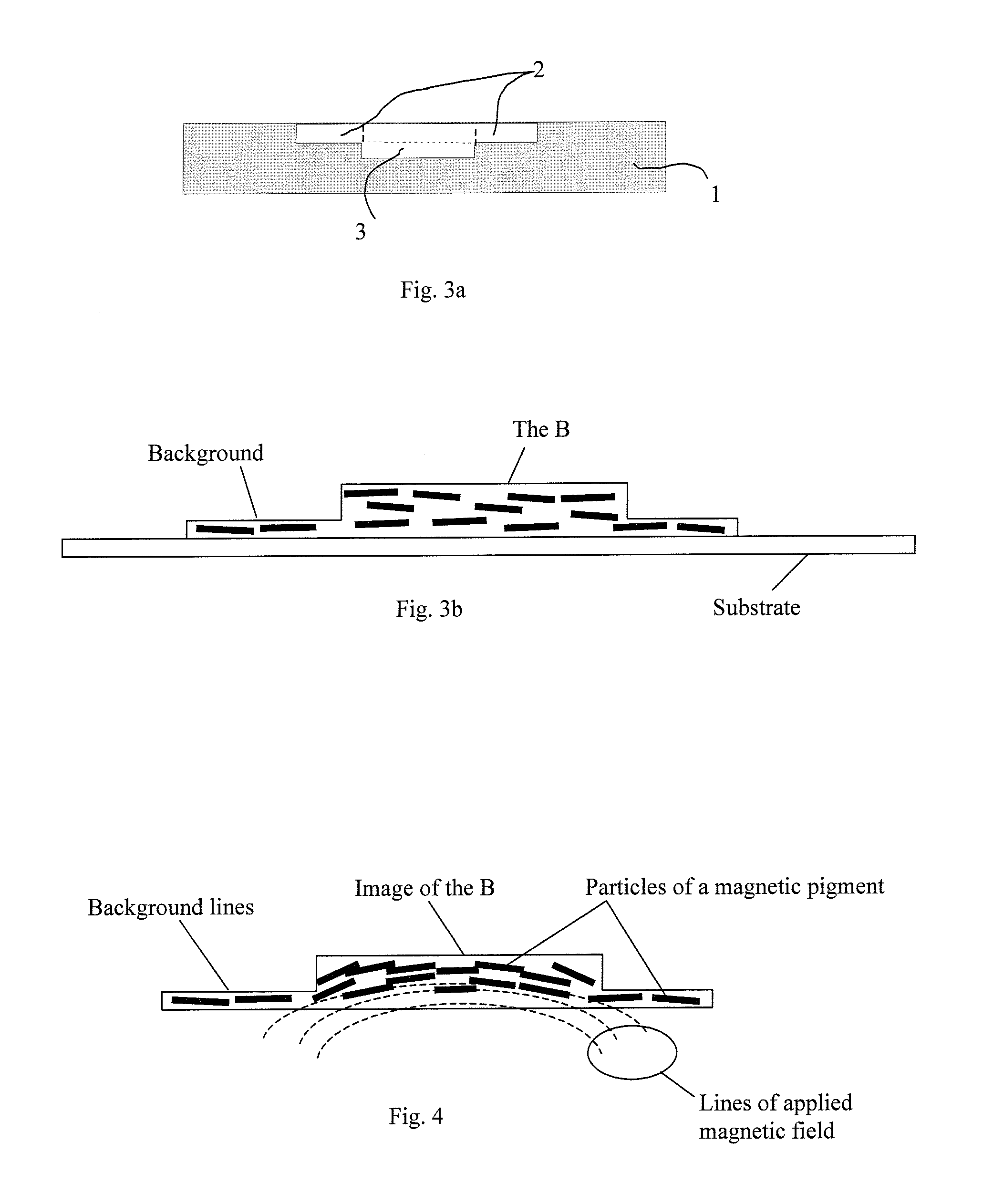
[0032]In this application the term optically variable encompasses effects that are color shifting, color switching, diffractive, or kinematic. Color shifting and switching effects are effects that change or switch color with a change in viewing angle of angle of incident light. Kinematic effects are those wherein the viewer “appears” to see an aspect of the image move, or wherein the color in one region “appears” to switch colors with another region. In an image having kinematic effects the viewer appears to see motion or depth that would not be seen in a uniform coating that merely exhibited color shifting. In a kinematic image flakes are magnetically aligned such that they are not all uniformly aligned. Thus, tilting or rotating provides the illusion of movement or change.

[0033]The term “visible” used hereafter is to mean visible with the human eye; that is, without magnification.

[0034]The term “line” used hereafter is to encompass a straight or curved solid line, dotted line, das...


PUM


Abstract

A security device is disclosed that has an image formed upon a substrate. The image has a first printed region and a second different printed region both printed with a same ink formulation of field alignable flakes. At least one of the printed regions has optically variable effects. One of the first and second printed regions at least partially surrounds the other. The second printed region is formed of thin parallel lines and the first printed region has substantially wider lines than are printed in the second printed region. The area density of the ink in a line in the first group of wider lines is greater than the area density of a line in the second group of narrower lines. A surprising effect of this image is that particles or flakes in the ink are field aligned so as to produce a visible kinematic dynamic effect visible in the first region and not visible in the second region when the image is tilted or rotated.

Description

CROSS-REFERENCE TO RELATED APPLICATIONS[0001]This Application claims priority of U.S. Provisional Patent Application No. 60 / 777,086 filed Feb. 27, 2006, entitled “Dynamic Appearance-Changing Optical Devices (DACOD) Printed In Shaped Magnetic Field And Printable Fresnel Structures” which is incorporated herein by reference for all purposes.FIELD OF THE INVENTION[0002]This invention relates to printing security devices upon a substrate and more particularly relates to a security device printed in one or more print passes that utilizes special effect magnetically aligned ink printed different line thicknesses in different regions to form an image wherein certain optical effects are seen within all lines, and wherein other optical effects are only seen in some lines or such areas as pixels, dots, dashed lines, etc. of a printed image in the absence of magnification as function of line thickness.BACKGROUND OF THE INVENTION[0003]Optically variable devices are used in a wide variety of app...

Claims


Application Information

Patent Timeline
30 Aug 2007
Publication
US20070200002A1
IPC
G06K19/06
CPC
B41M3/148; B42D2033/16; B42D25/29; B42D2035/24; B42D2035/16; B42D25/378; B42D25/00; B41M3/14
Inventors
RAKSHA, VLADIMIR P.; COOMBS, PAUL G.