Jacketed active magnetic bearing

a magnetic bearing and active technology, applied in the direction of bearings, shafts, dynamo-electric machines, etc., can solve the problems of differential thermal expansion between the jacket and the bearing housing, problems of electrical and magnetic coupling, and relatively large length of/b> bearings, so as to reduce the available load of bearings

Active Publication Date: 2007-08-30
SKF MAGNETIC MECHATRONICS
View PDF11 Cites 40 Cited by
  • Summary
  • Abstract
  • Description
  • Claims
  • Application Information

AI Technical Summary

Benefits of technology

[0032]The invention makes it possible to retain a conventional airgap, with values lying in the range about 0.3 mm to about 0.5 mm, between the first jacket and the armature of the bearing, without the available load of the bearing being reduced by the presence of the first and second jackets.

Problems solved by technology

The use of a single jacket 5 to define a leakproof wall both for the bearing and for the associated detector leads to making a jacket 5 of relatively great length, and that can lead to problems of differential thermal expansion between the jacket and the housing of the bearing.
Furthermore, the use of a single jacket that is common to the bearing and to the detector generally leads to problems of electrical and magnetic coupling, in particular in mean frequency ranges above 300 hertz (Hz).
The presence of such a jacket 5 of non-magnetic material thus amounts to increasing the thickness of the airgap of the bearing by about 100%, which leads to a significant limit on the load available from said bearing.

Method used


Image

  • Jacketed active magnetic bearing
  • Jacketed active magnetic bearing
  • Jacketed active magnetic bearing

Examples


Embodiment Construction

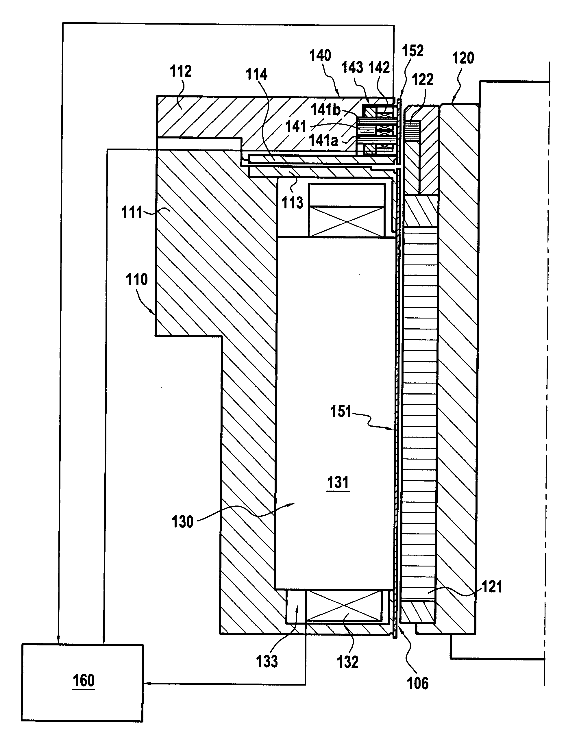
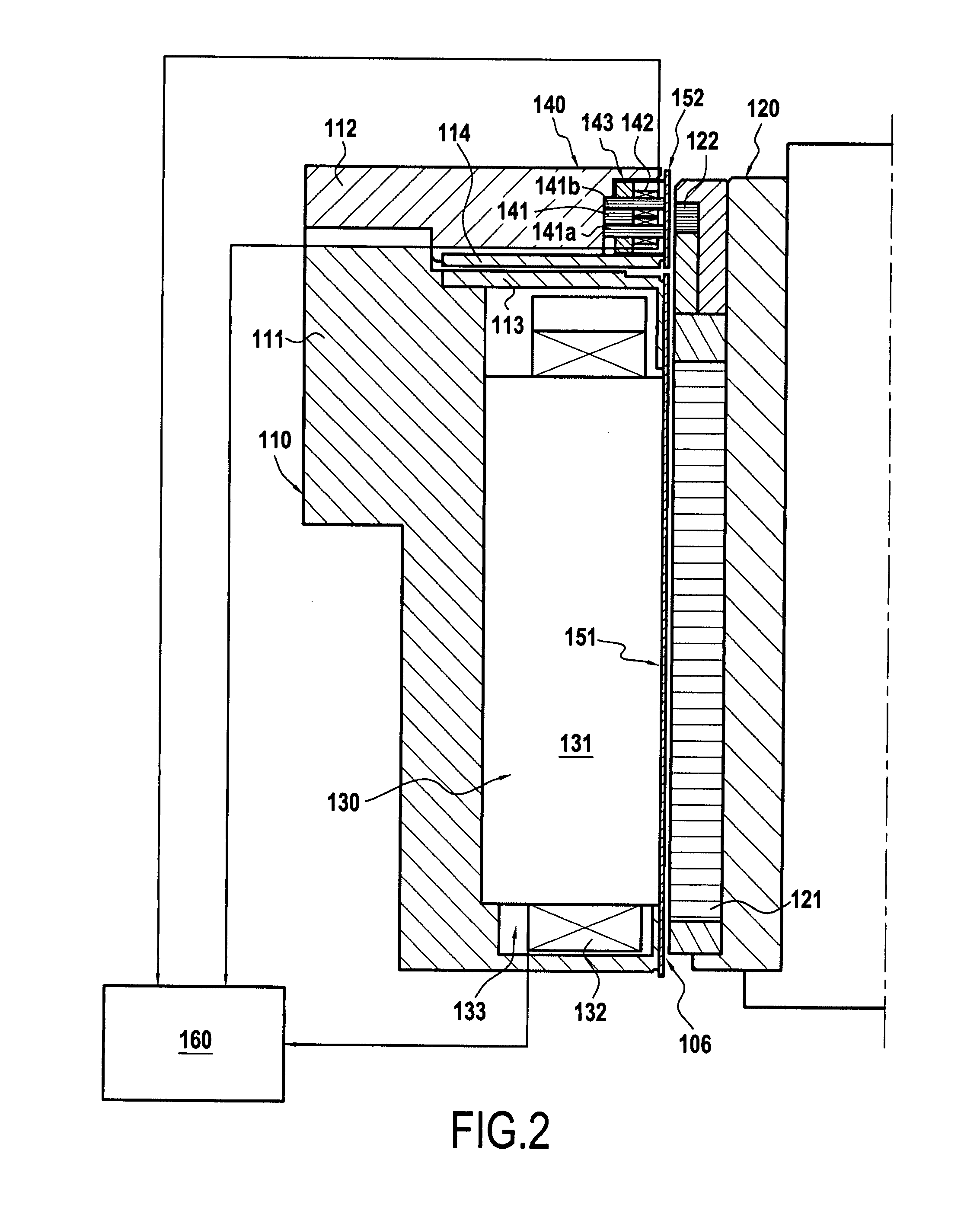
[0036]With reference to FIG. 2, there can be seen a rotor 120 of a rotary machine that is designed to be in contact with a process gas, which gas may be acid, corrosive, or a carrier of particles.

[0037]By way of example, the rotary machine may be a turboexpander for processing natural gas, a refrigerator compressor, or an electric motor for driving a compressor.

[0038]A bearing armature 121 of laminated magnetic material is applied to the rotor 120. This armature 121 may in particular make use of the 17 / 14 PH stainless material that is available in laminations of small thickness, in particular presenting a thickness of 0.2 mm.

[0039]A detector armature 122, likewise in laminated magnetic material, is fitted on the rotor 120, in the vicinity of the bearing armature 121. Like the armature 121, this armature 122 may be made of a 17 / 4 PH stainless material.

[0040]An airgap 106 presenting thickness that lies for example in the range 0.3 mm to 0.5 mm is provided firstly between the periphera...


PUM


Abstract

The jacketed active magnetic bearing is applied to a rotary machine having a rotor in contact with a process gas and placed in a leaktight enclosure. The magnetic stator is protected by a first jacket of magnetic anti-corrosion material that constitutes a portion of the leaktight enclosure and that is secured to the bearing stator, and the detector stator is protected by a second jacket of non-magnetic anti-corrosion material that constitutes a portion of the leaktight enclosure and that is secured to the detector stator. The bearing armature and the detector armature can be made of a laminated magnetic identical to that of the first jacket.

Description

[0001]The present invention relates to a jacketed active magnetic bearing for a rotary machine having a rotor in contact with a process gas and placed in a leaktight enclosure, the magnetic bearing comprising a bearing armature of laminated magnetic material secured to the rotor and placed inside said leaktight enclosure, a bearing stator made up of electromagnet windings associated with a yoke of laminated magnetic material that presents end pole pieces disposed at a short distance from said bearing armature but without making contact therewith, the bearing stator being disposed outside said leaktight enclosure, at least one position detector of the electromagnetic type comprising a detector armature of laminated magnetic material mounted on the rotor inside the leaktight enclosure and a detector stator comprising electromagnet windings associated with a yoke of laminated magnetic material, the detector stator being disposed outside said leaktight enclosure, and electronic control ...

Claims


Application Information

Patent Timeline
Patent Type & Authority Applications(United States)
IPC IPC(8): H02K11/00H02K5/12
CPCF16C32/047G01D11/245F16C2300/42F16C2240/40
Inventor BAUDELOCQUE, LUCLAPIERRE, ARMANDBRUNET, MAURICELACOUR, MICHEL
Owner SKF MAGNETIC MECHATRONICS
Why Eureka
Try Eureka