Method of setting stones in a support element

Active Publication Date: 2007-09-06
BLANCPAIN SA
View PDF3 Cites 7 Cited by
  • Summary
  • Abstract
  • Description
  • Claims
  • Application Information

AI Technical Summary

Benefits of technology

[0015]Owing to this method, the material of the decorated face of the support element located in proximity to the stones is not deformed and keeps a clean, smooth appearance. Moreover, the presence of the groove emphasises the alignment of the stones thereby increasing the aesthetic appeal of the whole of the decorated part. It will also be noted that this method allows finishing operations to be omitted, such as trimming and polishing the support element in the area of the grains insofar as this are is no longer visible from the decorated face side of the support element.
[0016]It will also be noted that, when one wishes to align stones in a groove, the method of the invention provides a simple and economical solution for achieving this, particularly by implementing a minimum

Problems solved by technology

This setting method has the drawback of deforming the material of the support element on the side of the decorated face such that it is unsuitable if one wishes to give a refined and unified appearance to a surface decorated with precious stones.
Thi

Method used


Image

  • Method of setting stones in a support element
  • Method of setting stones in a support element
  • Method of setting stones in a support element

Examples


Example

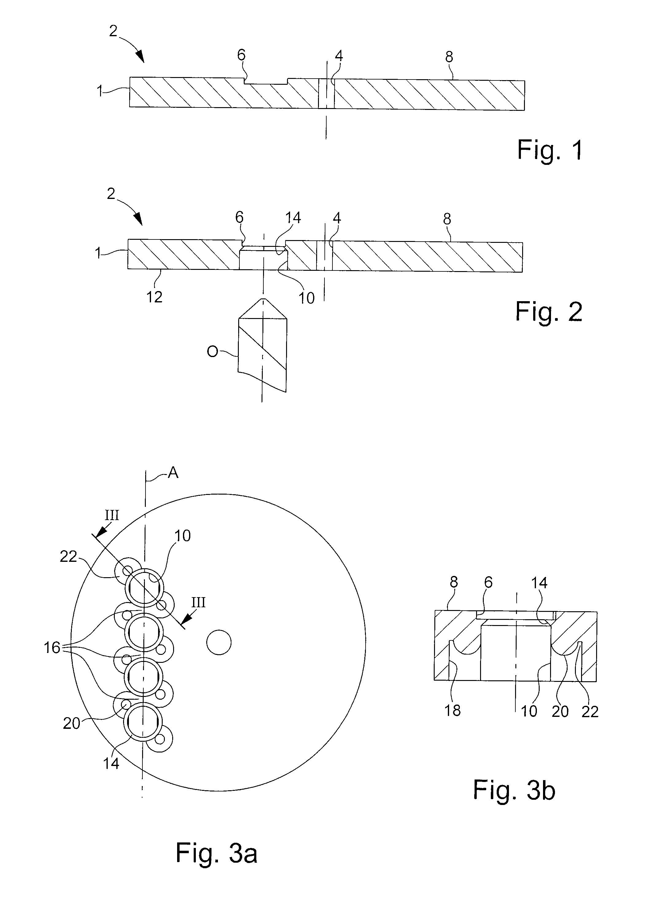
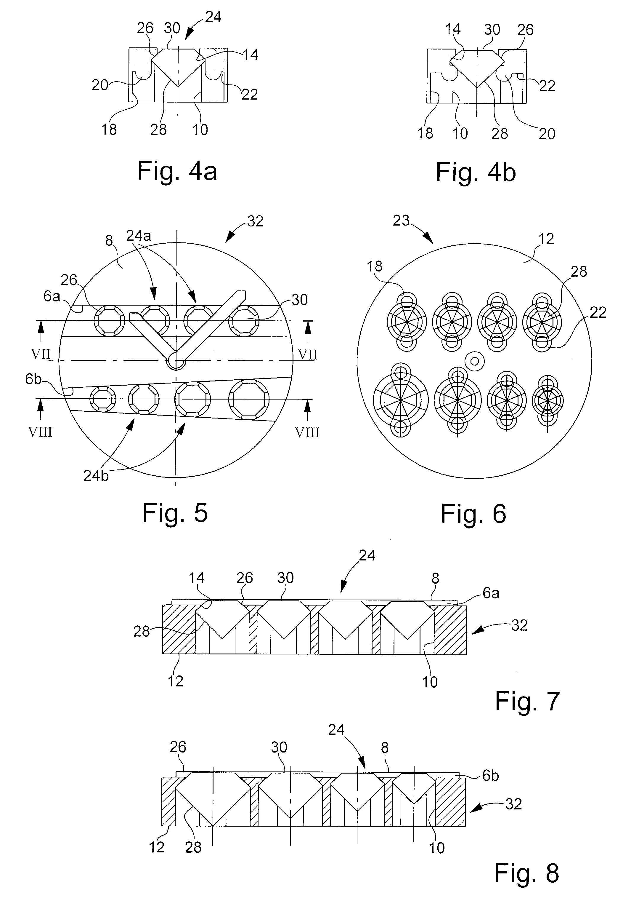
[0026]The setting method according to the invention will now be described within the scope of an application to making a timepiece dial having one face decorated with precious or semi-precious stones with reference to FIGS. 1 to 8.

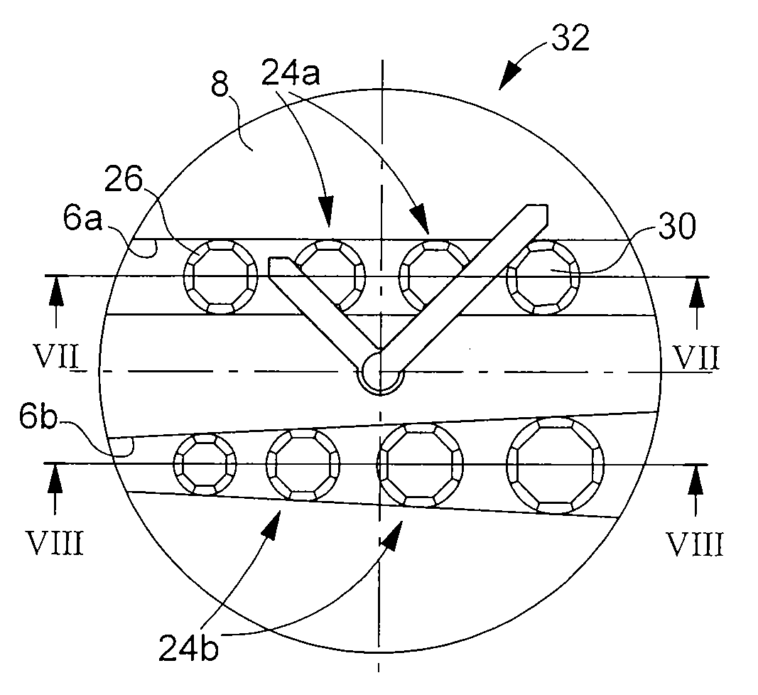
[0027]FIG. 1 shows a support element 1 taking the form of a metal plate for example of grey gold 150 several millimetres thick typically 1 mm and for making a dial 2 for a timepiece. Support element 1 includes, in a conventional manner, a hole 4 for the passage of the hands (not shown). Support element 1 further includes according to the process of the invention, at least one groove 6 made for example by milling, in the surface 8 which will form the decorated surface of dial 2. In the example illustrated, groove 6 is rectilinear and its width is constant, however, it goes without saying that, depending upon the desired appearance of the decorated surface, groove 6 can extend along a curved line of fixed or variable width, for example whose width flares fro...


PUM

PropertyMeasurementUnit
Massaaaaaaaaaa
Massaaaaaaaaaa
Diameteraaaaaaaaaa

Abstract

The invention concerns a method of setting a plurality of stones each having a culasse, a crown and a girdle in a metal support element including the steps of:
    • milling a groove on a first face of the support element;
    • piercing from a second face of the support element, opposite to said first face, a plurality of holes each having a diameter substantially corresponding to the diameter of the girdle of the stone that it will receive, such that each hole opens into said groove and the bottom of each hole forms a support wall for the crown of the stone;
    • forming grains in the second face of the support element in proximity to the support walls;
    • setting the stones in place in the holes such that the crown of each stone abuts against the support wall of the hole thereof; and
    • pushing the grains against the culasse of each stone in order to fix the stones in said support element.

Description

[0001]This application claims priority from European Patent Application No. 06110493.1, filed Feb. 28, 2006, the entire disclosure of which is incorporated herein by reference.FIELD OF THE INVENTION[0002]The present invention concerns a method of setting precious or semi-precious stones in a metal support element to produce pieces or jewelry or timepieces decorated with stones. The invention concerns more particularly a method of setting stones using grains in which the grains are not visible from the top of the decorated piece. The method of the invention is particularly suited to making dials set with a plurality of rows of stones, for timepieces.BACKGROUND OF THE INVENTION[0003]Various techniques for setting a plurality of precious stones on metal support elements are known within the field of jewelry and horology.[0004]One conventional method consists in piercing holes, with flared edges forming a shoulder, in the surface of the support element, in arranging the stones in the ho...

Claims


Application Information

Patent Timeline
IPC IPC(8): G04D3/00
CPCA44C17/04Y10T29/49588Y10T29/49579Y10T29/49583Y10T29/23Y10T29/49586A44C17/02A44C27/00
Inventor APPREDERISSE, ALANBUEHLER, JOHNNYMARCA, LIONEL A
Owner BLANCPAIN SA
Why Eureka
Try Eureka