Heat exchanger unit

a heat exchanger and unit technology, applied in the field of heat exchanger units, can solve the problems of air flow and heat transfer reduction

Inactive Publication Date: 2007-09-06
DELPHI TECH INC
View PDF25 Cites 42 Cited by
  • Summary
  • Abstract
  • Description
  • Claims
  • Application Information

AI Technical Summary

Benefits of technology

[0013]Accordingly, because the condensate is drained from the tubes, the condensate does not accumulate on the tubes and the fins. The prevention of the condensate from freezing maintains the free movement of air around the tubes of the heat exchanger and maintains the heat transfer capabilities of the heat exchanger.
[0014]In addition, the drainage of the condensate toward the common drainag

Problems solved by technology

As more condensate forms and freezes on the tubes and fins, the frozen condensate and the frost increase

Method used


Image

  • Heat exchanger unit
  • Heat exchanger unit
  • Heat exchanger unit

Examples


second embodiment

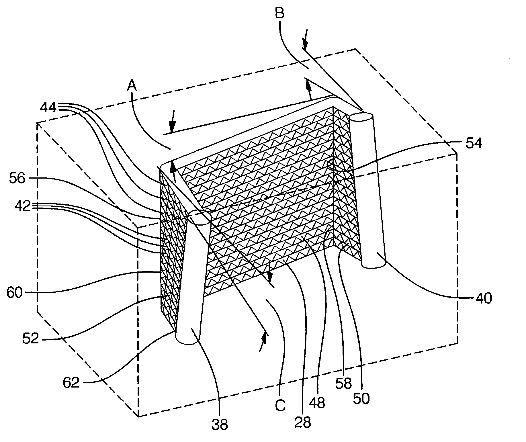
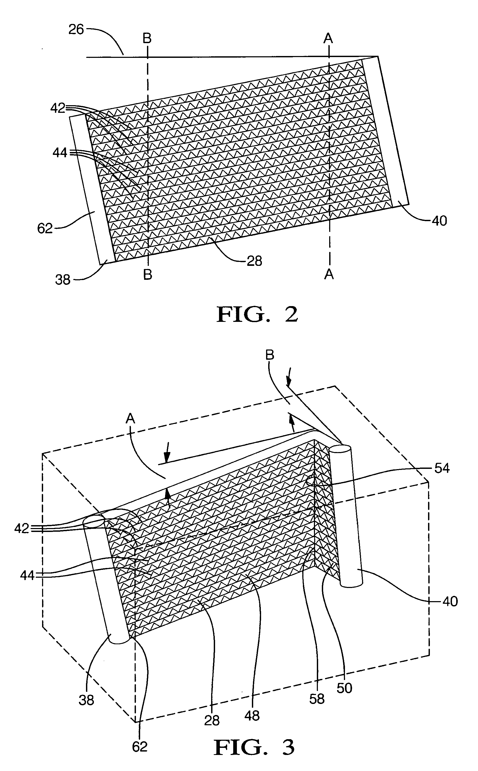
[0050]In the second embodiment, the second section 50 extends at a second angle B relative to the first plane 26. Preferably, the second angle is greater than or equal to 5 degrees.

[0051]In the second embodiment, the common drainage point 62 is located at the first manifold 38. In other words, condensate on the second section 50 of each of the tubes 42 drains along the second section 50 toward the first bend 54. This condensate at the first bend 54 as well as condensate on the first section 48 drains toward the first manifold 38. When the condensate reaches the first manifold 38, the condensate drips down the first manifold 38 to the common drainage point 62.

[0052]For illustrative purposes, FIG. 2 shows line A which corresponds to the first bend line 58. Specifically, line A extends angularly relative to the first manifold 38. Preferably, line A extends at the first angle A relative to the manifolds 38, 40. In such a configuration, when the first section 48 extends at the first angl...

fifth embodiment

[0058]In the heat exchanger, as shown in FIG. 6, each of the tubes 42 includes the first bend 54 connected to the first section 48 and the second section 50 extending from the first bend 54. The first bends 54 of each of the tubes 42 are spaced from one another along the first bend line 58. Preferably, the second section 50 extends perpendicularly relative to the first section 48. Each of the tubes 42 extend angularly from the first manifold 38 and from the second manifold 40.

[0059]In the fifth embodiment, as in the second embodiment, the second section 50 extends at a second angle B relative to the first plane 26. In the fifth embodiment, as in the second embodiment, the common drainage point 62 is located at the first manifold 38.

[0060]For illustrative purposes, FIG. 5 shows line C which correspond to the first bend line 58. Specifically, line C extends in parallel with the manifolds 38, 40. In such a configuration, when the first section 48 extends at the first angle A relative t...

seventh embodiment

[0064]In the heat exchanger, as shown in FIG. 8, each of the tubes 42 extend perpendicularly from the first manifold 38 and from the second manifold 40. Each of the tubes 42 includes the first bend 54 and the second bend 56 with the first section 48 extending between the first bend 54 and the second bend 56. The second section 50 extends from the first bend 54 and the third section 52 extends from the second bend 56. The first bend line 58, the second bend line 60, the first manifold 38, and the second manifold 40 extend in parallel.

[0065]As shown in FIG. 8, the second 50 and third 52 sections of each of the tubes 42 extends in parallel with the first plane 26 while maintaining the first section 48 at the first angle A relative to the first plane 26. In the seventh embodiment, the common drainage point 62 is located at the second bend line 60. In other words, condensate on each of the tubes 42 of the first section 48 drains along the first section 48 toward the second bend 56. When ...


PUM


Abstract

A heat exchanger unit includes a support assembly having a support surface extending in a first plane and a heat exchanger coupled to the support surface and fixed relative to the first plane. The heat exchanger includes a first manifold and a second manifold extending in spaced relationship with one another and a plurality of tubes spaced from one another and extending between and engaging the first manifold and the second manifold. The tubes communicate fluid between the manifolds. At least a portion of each of the tubes extend angularly relative to the first plane for draining condensate along the tubes toward a common drainage point to remove the condensate from the tubes and focus the condensate to the common drainage point. The drainage of the condensate from the tubes prevents the freezing of the condensate on the tubes to prevent the blockage of air movement over the tubes by frozen condensate.

Description

CROSS REFERENCE TO RELATED APPLICATION[0001]This application claims the benefit of Provisional Application Ser. No. 60 / 779,631 filed Mar. 6, 2006.BACKGROUND OF THE INVENTION[0002]1. Field of the Invention[0003]The present invention relates to a heat exchanger unit including a heat exchanger.[0004]2. Description of the Related Art[0005]Heat exchanger units are used in a variety of applications that require the transfer of heat from one space to another space. Specifically, the heat exchanger unit includes a heat exchanger and a support assembly for supporting the heat exchanger. Heat transfers from ambient air surrounding the heat exchanger to fluid, i.e. refrigerant, in the heat exchanger. Specifically, the heat exchanger includes a plurality of tubes. The fluid passes through the tubes and heat is transferred from the air surrounding the tubes to the fluid. Fins are generally disposed on the tubes to increase the surface area to the tubes to increase heat transfer from the air surr...

Claims


Application Information

Patent Timeline
IPC IPC(8): F24B1/06F25D21/00
CPCF28D1/05366F28F17/005F28D2001/0273
Inventor BEAMER, HENRY EARL
Owner DELPHI TECH INC
Why Eureka
Try Eureka