
Image Generating Apparatus

Inactive Publication Date: 2007-09-06
FUNAI ELECTRIC CO LTD
View PDF7 Cites 1 Cited by
  • Summary
  • Abstract
  • Description
  • Claims
  • Application Information

AI Technical Summary

Benefits of technology

[0014]In the image generating apparatus according to the aforementioned first aspect, a first end of the rotary shaft is preferably mounted on a shaft fixing portion, and the stop portion of the spring mount portion preferably includes a circumferential rib provided on an outer circumference of the spring mount portion of the take-up member closer to the shaft fixing portion. According to this structure, when the take-up member mounted with the spring member tries to move in a falling direction from the rotary shaft, the circumferential rib can easily inhibit the spring member from falling from the take-up member.
[0029]In the image generating apparatus according to the aforementioned second embodiment, the guide portion is preferably so formed that a notch width is gradually increased from the bottom portion of the notch toward the open end of the notch. According to this structure, the first end of the spring member inserted into the open end with the large notch width is guided by the guide portion to reach the bottom portion with the small notch width. Thus, the spring member can be easily engaged with the spring engaging portion.

Problems solved by technology

However, the aforementioned take-up member described in Japanese Patent Laying-Open No. 2005-199520 is provided with a retaining ring for inhibiting the take-up member from falling from the rotary shaft, and therefore a stop member (retaining ring) is disadvantageously separately required.
The aforementioned print head unit described in Japanese Patent Laying-Open No. 2002-187322 is not fixed to the rotary shaft, and therefore the print head unit disadvantageously falls from the image generating apparatus.
Thus, in a case where the aforementioned structure of the print head unit in Japanese Patent Laying-Open No. 2002-187322 is employed for regulating the rotation of the take-up member for taking up an ink sheet, the take-up member disadvantageously falls.

Method used


Image

  • Image Generating Apparatus
  • Image Generating Apparatus
  • Image Generating Apparatus

Examples


Embodiment Construction

[0042]An embodiment of the present invention will be hereinafter described with reference to the drawings.

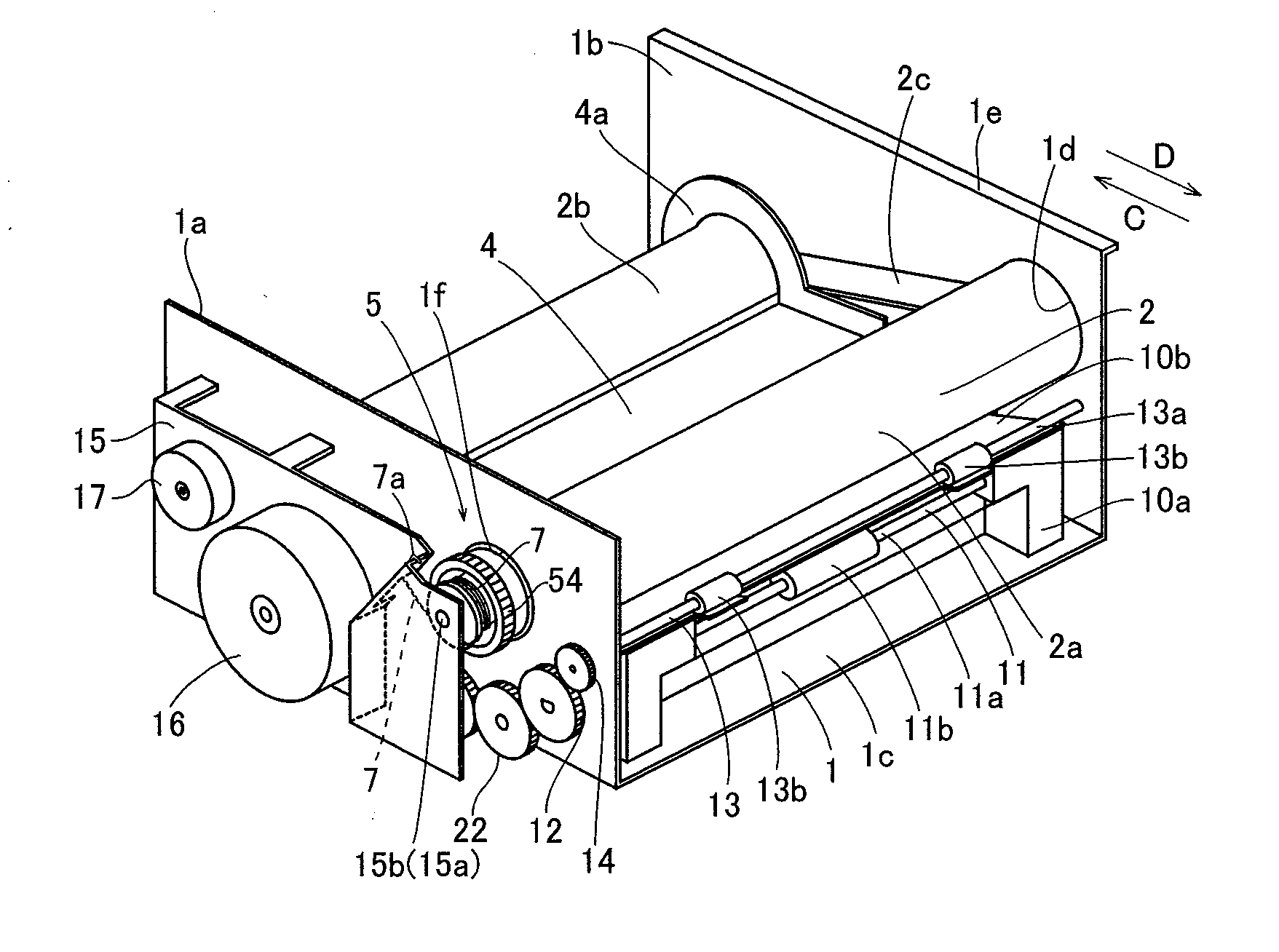
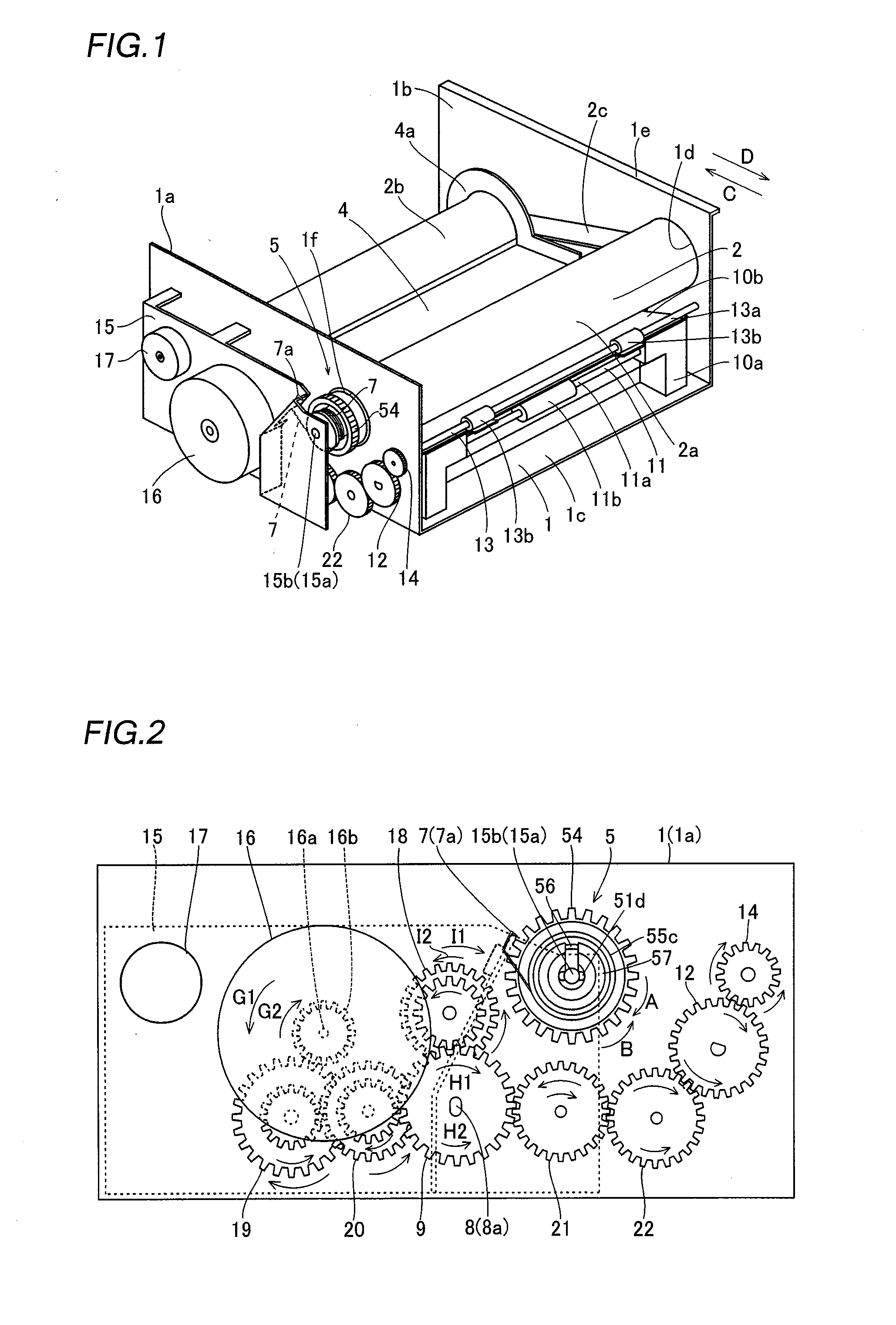
[0043]A structure of a thermal transfer printer according to the embodiment of the present invention will be now described with reference to FIGS. 1 to 10. According to this embodiment, the present invention is applied to the thermal transfer printer, which is an exemplary image generating apparatus.

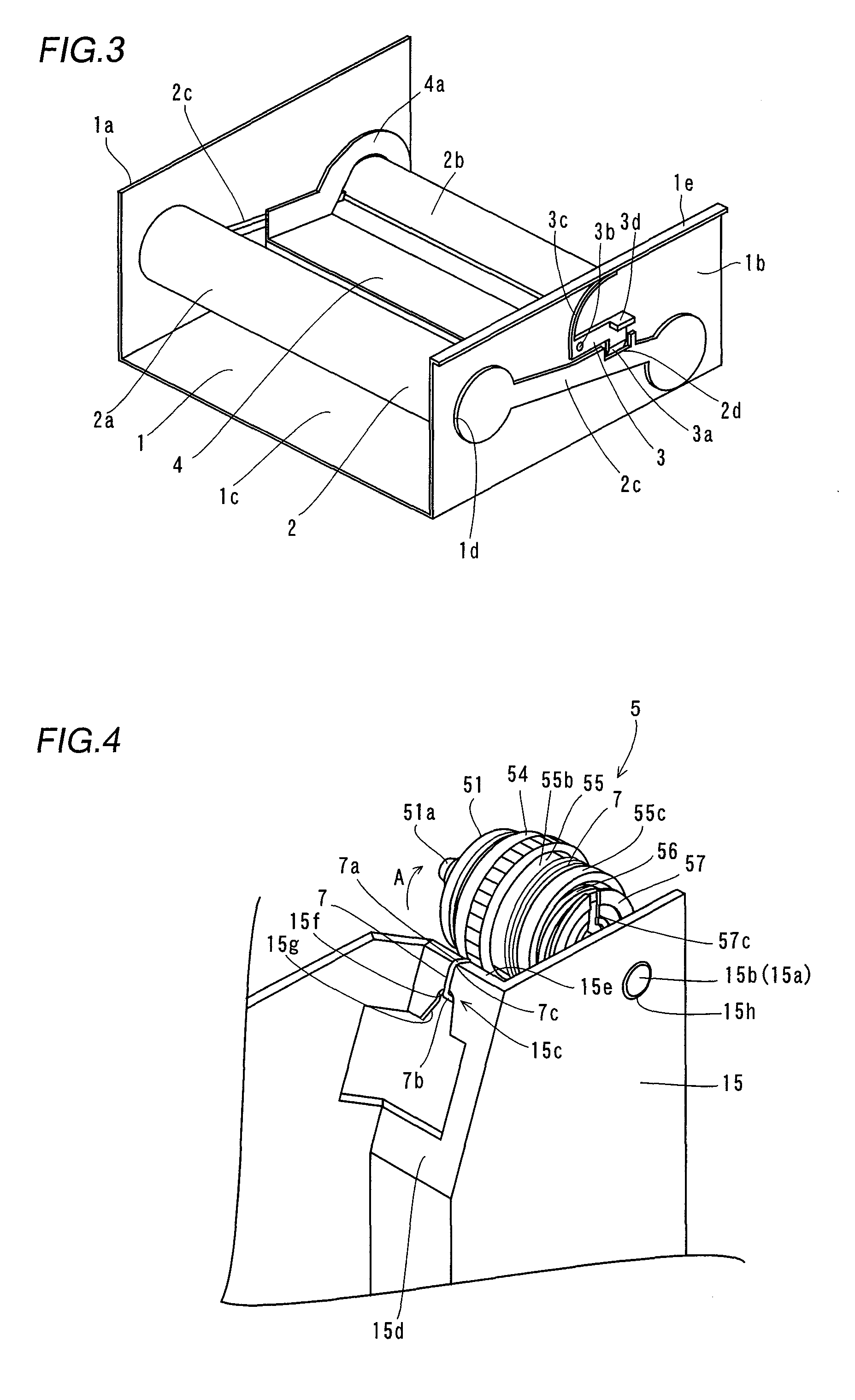
[0044]The thermal transfer printer according to the embodiment comprises a chassis 1 made of metal, a stopper member 3 (see FIG. 3) for fixing an ink sheet cartridge 2, a print head 4 for printing, a take-up reel 5 (see FIGS. 1 and 2) and a feed reel 6 (see FIG. 10) engaged with the ink sheet cartridge 2, a spring member 7 regulating a direction of rotation of the take-up reel 5, a feed roller 8 (see FIG. 2), a feed roller gear 9 (see FIG. 2), a lower paper guide 10a made of resin, an upper paper guide 10b made of resin, a paper feed roller 11, a paper feed roller gear 12, a paper di...


PUM


Abstract

An image generating apparatus capable of inhibiting a take-up member from falling without separately providing a stop member is obtained. This image generating apparatus includes a take-up member for taking up an ink sheet, including a spring mount portion, a rotary shaft rotatably inserted into the take-up member, a spring member for regulating the take-up member to rotate only in a take-up direction, mounted on the spring mount portion of the take-up member, and a spring engaging portion engaged with a first end of the spring member. The spring mount portion of the take-up member is integrally provided with a stop portion for inhibiting the spring member from falling.

Description

BACKGROUND OF THE INVENTION[0001]1. Field of the Invention[0002]The present invention relates to an image generating apparatus, and more particularly, it relates to an image generating apparatus comprising a take-up member for taking up an ink sheet, including a spring mount portion, and a spring member for regulating the take-up member to rotate only in a prescribed direction, mounted on the spring mount portion of the take-up member.[0003]2. Description of the Background Art[0004]An image generating apparatus comprising a take-up member for taking up an ink sheet, including a spring mount portion, and a spring member for regulating the take-up member to rotate only in a prescribed direction, mounted on the spring mount portion of the take-up member is known in general, as disclosed in Japanese Patent Laying-Open No. 2005-199520, for example.[0005]In a take-up member described in the aforementioned Japanese Patent Laying-Open No. 2005-199520, a spring member for regulating the take...

Claims


Application Information

Patent Timeline
IPC IPC(8): B41J2/01
CPCB41J2/32
Inventor MUSHIMOTO, ATSUSHI
Owner FUNAI ELECTRIC CO LTD
Learn More