Powered Compression Clamping System

Pending Publication Date: 2022-03-10
MARTIN MATT
View PDF0 Cites 0 Cited by
  • Summary
  • Abstract
  • Description
  • Claims
  • Application Information

AI Technical Summary

Benefits of technology

[0016]It is an object of this invention to provide a wrench which may be easily engaged to one or a

Problems solved by technology

However, such conventional handle and worm gear driven systems can be slow and tedious.
Where multiple such clamping systems are located, such as on a construction or job site, the ongoing need to rotate the m

Method used


Image

  • Powered Compression Clamping System
  • Powered Compression Clamping System
  • Powered Compression Clamping System

Examples


Example

[0030]In this detailed description, the directional prepositions of up, upwardly, down, downwardly, front, back, top, upper, bottom, lower, left, right and other such terms refer to the device as it is oriented and appears in the drawings and are used for convenience only. Any such terms are not intended to be limiting or to imply that the device has to be used or positioned in any particular orientation.

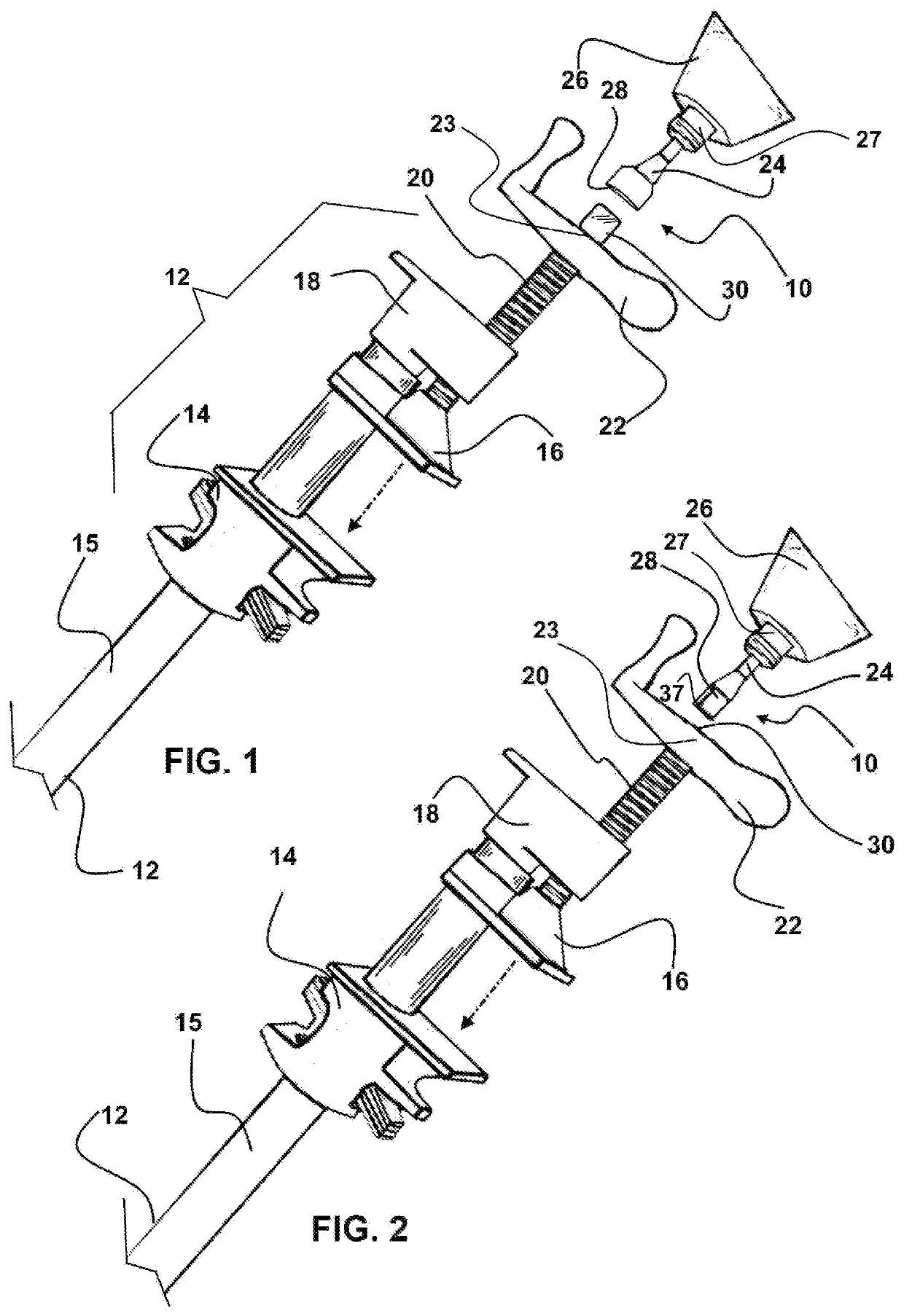
[0031]Referring now to the device 10 herein shown in the depictions of FIGS. 1-12, there is shown in FIG. 1 a conventional clamp 12 which has a first jaw 14 in a fixed engagement to a member 15 such as a pipe. A second jaw 16 is shown slidably engaged on the member 15 adjacent to a body portion 18 which is in a fixed connection to the member 15.

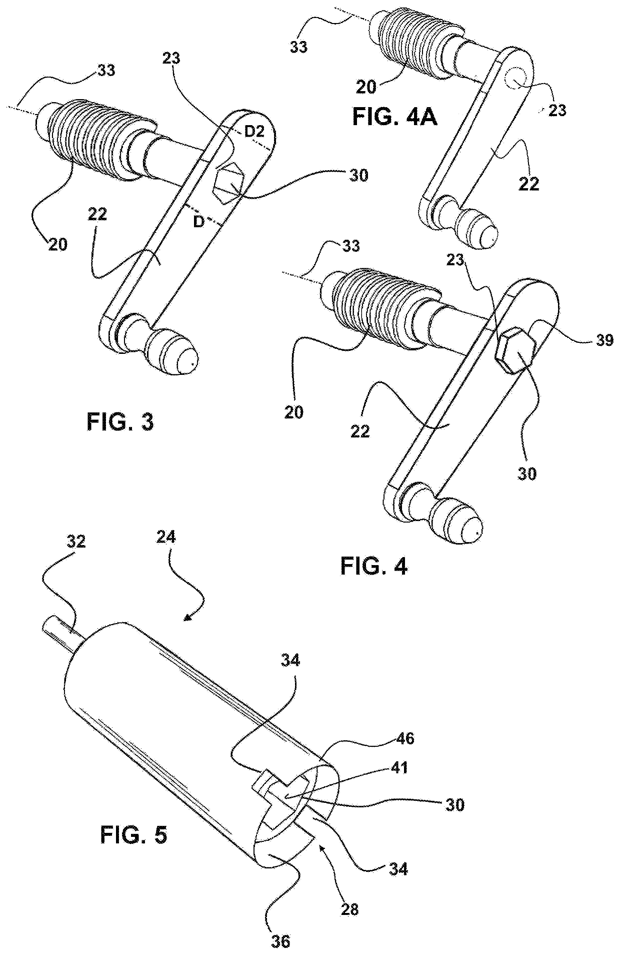
[0032]The second jaw 16 is connected to the distal end of a worm gear 20. The worm gear 20 is threadably engaged with the body portion 18 and has a handle 22 connected at a first end of the worm gear 20. Rotation of the handle 22 rotates the ...


PUM


Abstract

A powered compression clamping system is provided by a wrench which is engageable to a power tool such as a drill on a first end. A second end of the wrench has a connector thereon which is configured to removably engage a handle of a clamp to rotate it using the power tool.

Description

[0001]This application claims priority to U.S. Provisional Patent Application Ser. No. 63 / 076,122 filed on Sep. 9, 2020, which in included herein in its entirety by this reference thereto.BACKGROUND OF THE INVENTION1. Field of the Invention[0002]The invention herein disclosed relates generally to compression clamping systems. More particularly, it relates to a device and system enabling both powered and hand operation of handles employed to operate such clamping systems in woodworking and as widely employed on construction sites.2. Prior Art[0003]In the field of woodworking and construction and other endeavors, compression clamping systems are employed to hold components in appropriate positions temporarily, such as when adhering layers of wood material to each other and to hold components in place which are to be engaged using fasteners. Conventionally, a clamping system is employed for such projects which is configured with mechanical advantage which allows the user to compress co...

Claims


Application Information

Patent Timeline
IPC IPC(8): B25B21/00
CPCB25B21/002B25B5/102B25B5/101B25B13/5091B25B23/00
Inventor MARTIN, MATT
Owner MARTIN MATT
Why Eureka
Try Eureka