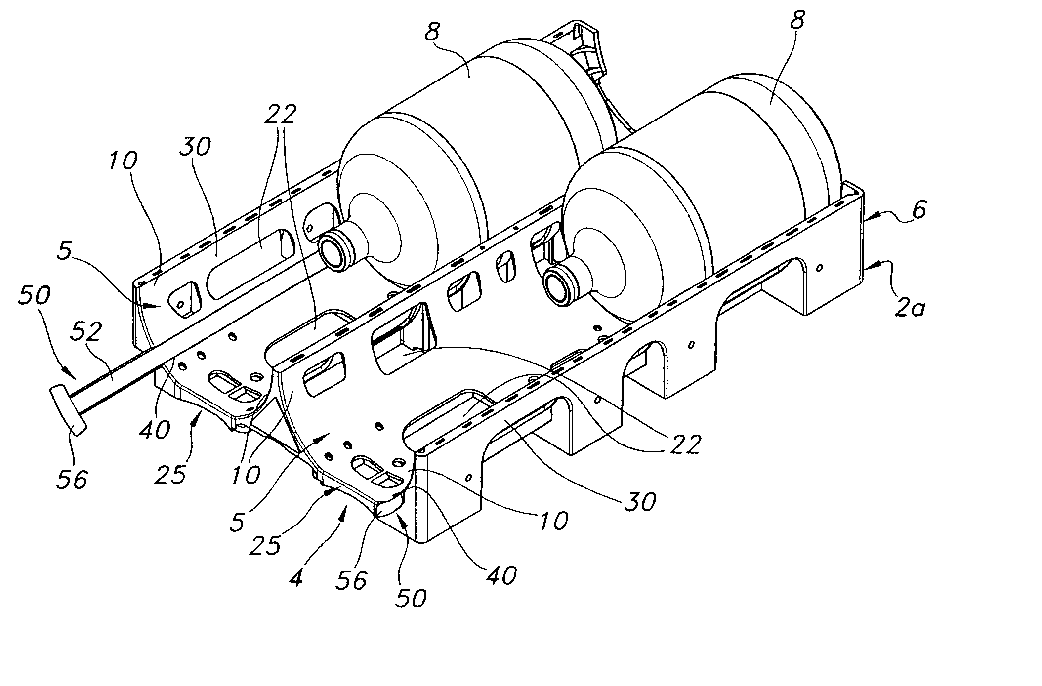
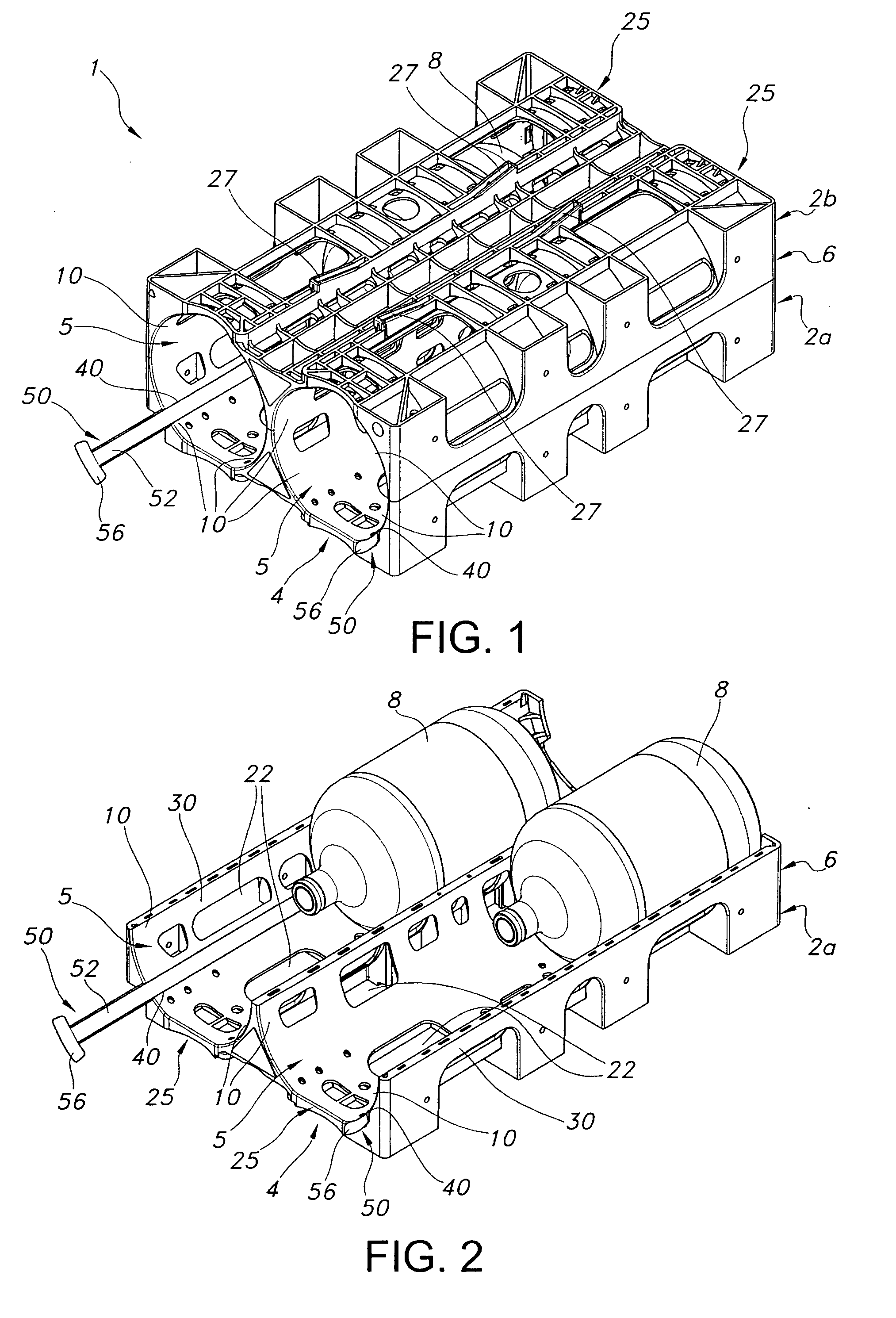
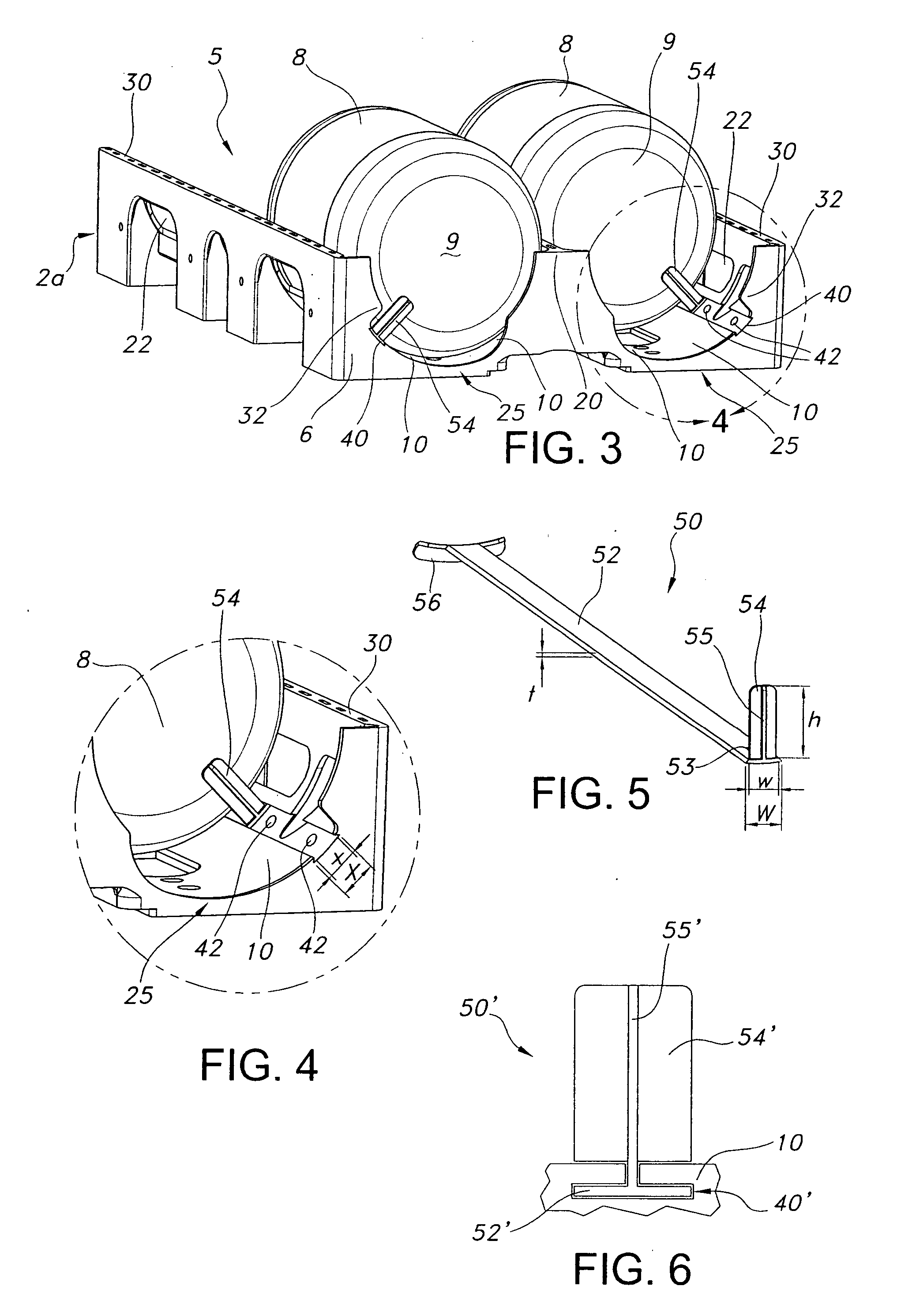
Storage rack with puller assembly

a technology of puller assembly and storage rack, which is applied in the field of racks, can solve the problems of difficult access and potential danger, and achieve the effect of reducing the chance of disengagement of the engagement member from the storable member during movemen

Inactive Publication Date: 2007-09-06
KELLY DANIEL
View PDF44 Cites 11 Cited by
  • Summary
  • Abstract
  • Description
  • Claims
  • Application Information

AI Technical Summary

Benefits of technology

[0006] To meet these and other needs, and in view of its purposes, an exemplary embodiment of the present invention provides a storage rack comprising a storage unit housing defining at least one aperture extending longitudinally between a forward end and a rearward end. The aperture is adapted to receive at least one storable member. A puller assembly is positioned in the aperture. The puller assembly includes a longitudinal puller body that supports an engagement member adjacent a rear end thereo

Problems solved by technology

Such access is difficult, and potentially dangerous, particularly for

Method used


Image

  • Storage rack with puller assembly
  • Storage rack with puller assembly
  • Storage rack with puller assembly

Examples


first embodiment

[0053] In operation, the handle 76 is moved into engagement with the storage unit front surface 4, thereby positioning each engagement member 74 in the rear of a respective aperture 5. Storable members 8 are positioned in the apertures 5 with the engagement members 74 engaging rearward surfaces 9 of the storable members 8. Forward movement of the handle 76 causes both engagement members 74 to move forward, thereby moving the storable members 8 forward. If only one of the apertures 5 contains a rearwardly positioned storable member 8, then only that one storable member 8 will be moved forward. As in the first embodiment, the guide slots 40″ support the respective engagement members 74 and prevent disengagement from the storable members 8. Again, since the puller bodies 72 are recessed within respective guide slots 40″, the puller assembly 70 does not interfere with movement of the storable members 8.

[0054] The puller assembly 70 is preferably manufactured from a polymeric material, f...

second embodiment

[0056] Each puller assembly 80 includes a longitudinal body 82 extending between a handle 86 and an engagement member 84. As in the second embodiment, engagement member 84 includes a longitudinally extending contact portion 83 and a radially extending contact portion 85. The longitudinally extending contact portion 83 does not sit upon the puller body 82, but instead is formed co-planar therewith such that the puller assembly 80 has a smooth lower surface 87, as best seen in FIG. 17. The puller assembly 80 does not include a dovetail or the like configured to engage a slot, but instead the smooth lower surface 87 is configured to be positioned on and move along the inside surface of the aperture 5. In the present embodiment, the puller body 82 has a wider, arcuate configuration such that the puller body 82 engages a larger arc of the aperture 5 inner surface. Additionally, the longitudinally extending contact portion 83 has a wide, arcuate configuration that complements the inner su...


PUM


Abstract

A storage rack comprising a storage unit housing defining at least one aperture extending longitudinally between a forward end and a rearward end. A puller assembly is positioned in the aperture and includes a longitudinal puller body that supports an engagement member adjacent a rear end thereof. The puller assembly is moveable between a first position in which the engagement member is adjacent the aperture rearward end and a second position in which the engagement member is moved toward the aperture forward end. The storage unit housing and the puller assembly are configured such that the engagement member is supported during movement between the first and second positions.

Description

[0001] This application claims the benefit of U.S. Provisional Application No. 60 / 752,296, filed Dec. 21, 2005.BACKGROUND OF THE INVENTION [0002] This invention relates generally to a rack for storing storable members, such as water bottles, and more specifically to storage units having a puller assembly for facilitating removal of the storable members from the storage unit. [0003] One example of a storable member typically stored and transported in racks is a generally cylindrical water bottle. These water bottles are typically handled, transported, and stored in varying quantities. For easier handling, transport, and storage, the water bottles may be loaded in carriers designed to accommodate multiple bottles. Each carrier defines one or more apertures configured to receive and support the bottles in a horizontal position. To accommodate a larger number of bottles, each aperture is typically configured to receive two bottles, one behind the other. To further accommodate the varyin...

Claims


Application Information

Patent Timeline
IPC IPC(8): G11B23/03
CPCA47B81/007B65G1/06B60P3/055
Inventor DONNELL, EMERSON B.KELLY, DANIEL
Owner KELLY DANIEL
Why Eureka
Try Eureka