
Light emitting diode based products

a technology of light-emitting diodes and products, applied in the field of light-emitting diodes based products, can solve the problems of limited accessories, limited lighting, and limited lighting of existing illuminated systems, and achieves the effects of reducing the number of lamps, and reducing the cost of production

Inactive Publication Date: 2007-09-06
SIGNIFY NORTH AMERICA CORP
View PDF99 Cites 294 Cited by
  • Summary
  • Abstract
  • Description
  • Claims
  • Application Information

AI Technical Summary

Benefits of technology

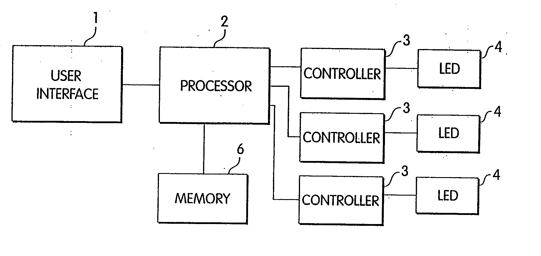
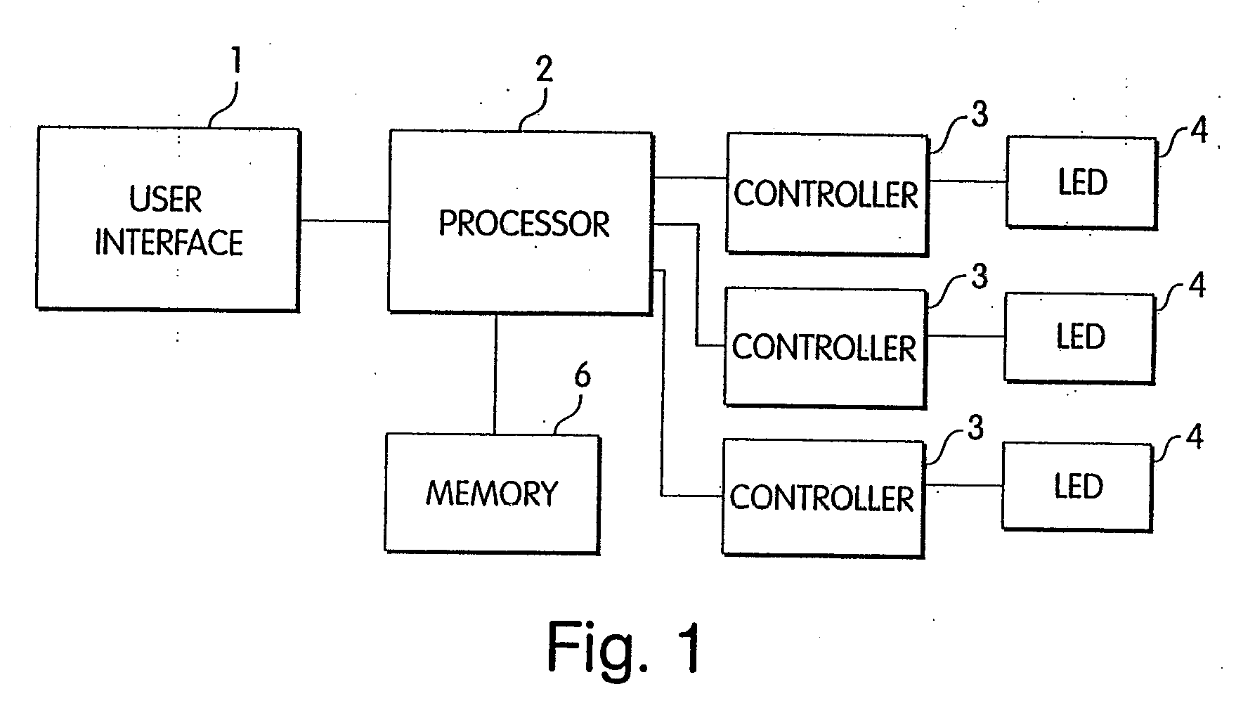
[0019] High-brightness LEDs, combined with a processor for control, can produce a variety of pleasing effects for display and illumination. Systems disclosed herein use high-brightness, processor-controlled LEDs in combination with diffuse materials to produce color-changing effects. The systems described herein may be usefully employed to bring autonomous color-changing ability and effects to a variety of consumer products and other household items. The systems may also include sensors so that the illumination of the LEDs may change in response to environmental conditions or a user input. Additionally, the systems may include an interface to a network, so that the illumination of the LEDs may be controlled via the network.

Problems solved by technology

Existing illuminated systems, however, are generally only capable of exhibiting fixed illumination with one or more light sources.
Such accessories, however, remain limited to a small number of different colored states, for example, three distinct illumination colors: red (red bulb illuminated); blue (blue bulb illuminated); and purple (both red and blue bulbs illuminated).
While these references teach systems for producing lighting effects, they do not address some applications of programmable, multi-colored lighting systems.
There are toy balls that have lighted parts or balls where the entire surface appears to glow; however there is no ball available that employs dynamic color changing effects.
Moreover, there is no ball available that responds to data signals provided from a remote source.
As a significant disadvantage, these systems apply complicated wiring harnesses to achieve dynamic lighting.

Method used


Image

  • Light emitting diode based products
  • Light emitting diode based products
  • Light emitting diode based products

Examples


Embodiment Construction

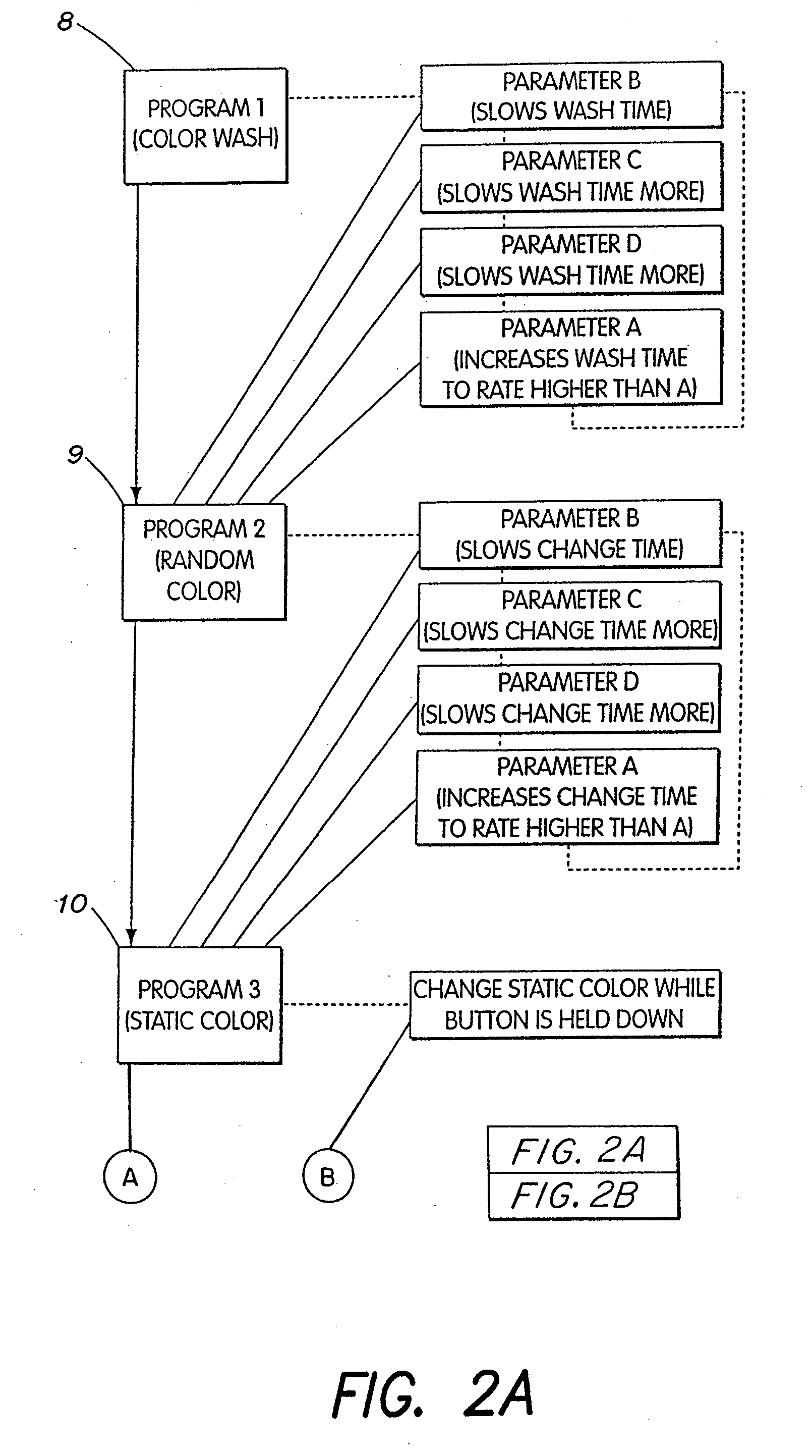
[0070] Various exemplary implementations of light emitting diode (LED) based illumination products and methods are disclosed including, but not limited to, glow sticks, key chains, toys, balls, various game accessories, light bulbs, night lights, wall lights, wall switches, wall sockets, wall panels, modular lights, flexible lights, automotive lights, wearable accessories, light ropes, decorative lights such as icicles and icicle strings, light tubes, insect control lights and methods, and illuminated air fresheners / scent dispensers. Any of the foregoing devices may be equipped with various types of user interfaces (both “local” and “remote”) to control light generated from the device. Additionally, devices may be controlled via light control information or programs stored in device memory and / or transmitted or downloaded to the devices (e.g., devices may be controlled individually or collectively in groups via a network, glow sticks or other products may be downloaded with programm...


PUM


Abstract

Methods and apparatus for downloading one or more lighting programs including one or more lighting effects. The lighting program(s) may be downloaded from a web site to one or more LED-based lighting devices that are configured to execute the downloaded lighting program(s) so as to reproduce the lighting effect(s). In various examples, a variety of programming devices may be employed to facilitate wired or wireless downloading, including one or more computers, personal digital assistants (PDAs), cell phones, media players (e.g., MP3 players), and the like. Information may be uploaded to the web site to facilitate selection and / or creation of lighting effect(s) that are included in the downloaded lighting program(s).

Description

CROSS-REFERENCE TO RELATED APPLICATIONS [0001] This application claims the benefit under 35 U.S.C. §120 as a continuation of U.S. Non-provisional application Ser. No. 11 / 106,381, filed Apr. 14, 2005, entitled “Light Emitting Diode Based Products.”[0002] Ser. No. 11 / 106,381 claims the benefit under 35 U.S.C. §120 as a continuation of U.S. Non-provisional application Ser. No. 10 / 245,786, filed Sep. 17, 2002, entitled “Light Emitting Diode Based Products.”[0003] Ser. No. 10 / 245,786 claims the benefit under 35 U.S.C. §119(e) of the following U.S. Provisional Applications: [0004] Ser. No. 60 / 322,765, filed Sep. 17, 2001, entitled “Light Emitting Diode Illumination Systems and Methods”; [0005] Ser. No. 60 / 329,202, filed Oct. 12, 2001, entitled “Light Emitting Diode Illumination Systems and Methods”; [0006] Ser. No. 60 / 341,476, filed Oct. 30, 2001, entitled “Systems and Methods for LED Lighting”; [0007] Ser. No. 60 / 335,679, filed Oct. 23, 2001, entitled “Systems and Methods for Programmed ...

Claims


Application Information

Patent Timeline
IPC IPC(8): F21S8/00
CPCA43B1/0027F21K9/50A43B3/0021F21S8/035F21W2121/006F21Y2101/02G02B6/001G02B6/0031G02B6/0036G02B6/0043G02B6/0055G02B6/006G02B6/0061H05B37/029F21V23/0464A43B3/001F21V3/04F21K9/135A43B3/0005F21K9/232F21K9/60F21Y2115/10H05B47/155A43B3/36A43B3/50A43B3/34
Inventor PIEPGRAS, COLINMUELLER, GEORGE G.LYS, IHOR A.DOWLING, KEVIN J.MORGAN, FREDERICK M.
Owner SIGNIFY NORTH AMERICA CORP
Learn More