
Circuit board having functions for detecting and adjusting junction current or voltage and electronic apparatus having the circuit board

Active Publication Date: 2007-09-06
HITACHI LTD
View PDF8 Cites 5 Cited by
  • Summary
  • Abstract
  • Description
  • Claims
  • Application Information

AI Technical Summary

Benefits of technology

[0006]Generally, an exciting source of the unnecessary electromagnetic wave radiated from the circuit board sole body is an element such as LSI, crystal oscillator, or the like. An antenna which radiates an electromagnetic energy into the air often has a pattern

Problems solved by technology

However, even if the EMI countermeasure of the circuit board sole body is completely taken as mentioned above, there is such a problem that at a point of time when the circuit board is mounted on the casing (frame, chassis, or the like) for enclosing the board, a level of the unnecessary electromagnetic radiation changes and a new EMI countermeasure is necessary.
As for such a problem, in many cases, a correlation between a measurement result of the neighborhood magnetic field on the board and a far field upon mounting of the casing cannot be obtained and it takes a time for the countermeasure in the circuit board.
Even if it is intended to take the EMI countermeasure on the casing side, generally, since the casing often has a three-dimensional complicated shape, it is difficult to measure the current distribution, so that it takes a time and costs are high.
Further, also in the case of inserting the filter into the junction between the circuit board and the casing, since a path of the current which becomes the cause of the casing radiation as a target to be reduced and electric characteristics are obscure, it is difficult to promptly obtain effective characteristics.

Method used


Image

  • Circuit board having functions for detecting and adjusting junction current or voltage and electronic apparatus having the circuit board
  • Circuit board having functions for detecting and adjusting junction current or voltage and electronic apparatus having the circuit board
  • Circuit board having functions for detecting and adjusting junction current or voltage and electronic apparatus having the circuit board

Examples


Embodiment Construction

[0027]The invention relates to a circuit board for measuring a current flowing out from the circuit board to a casing or an electronic apparatus in a junction of the circuit board and enabling the current to be adjusted.

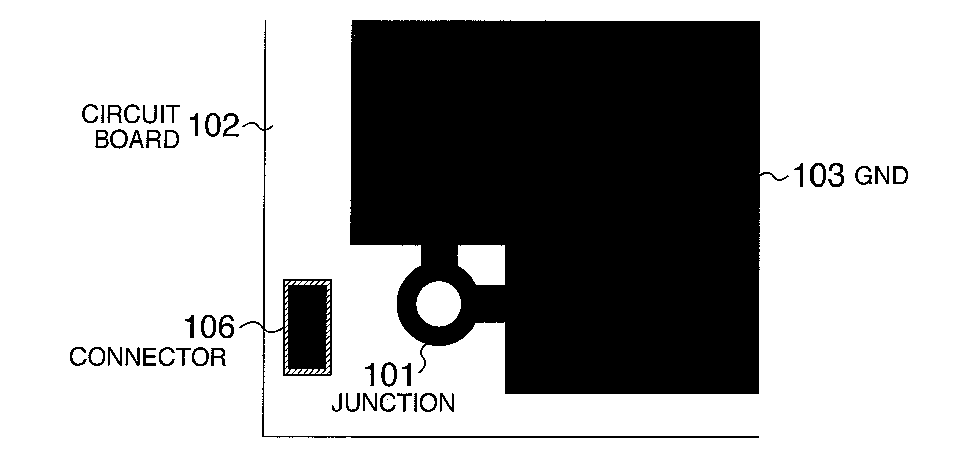
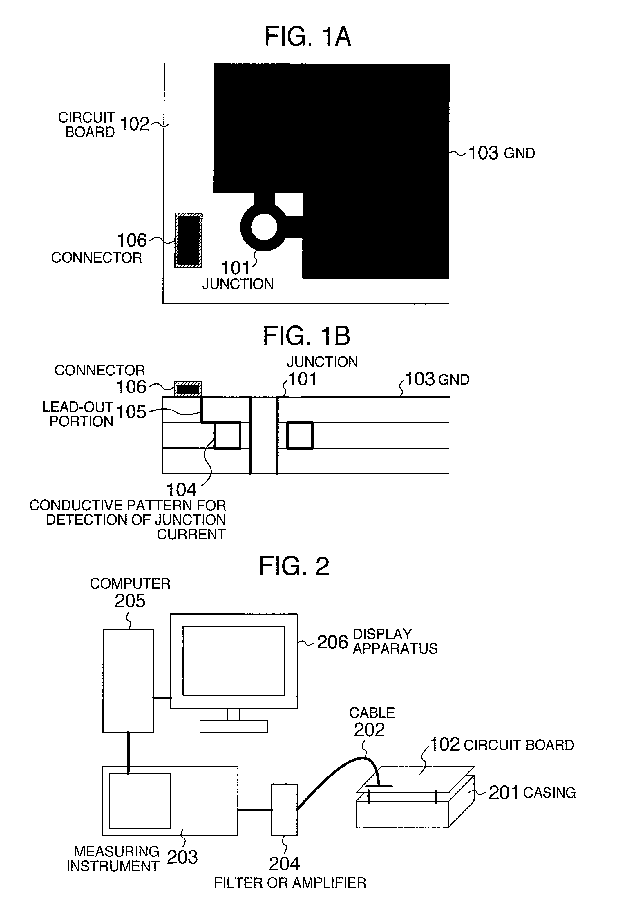
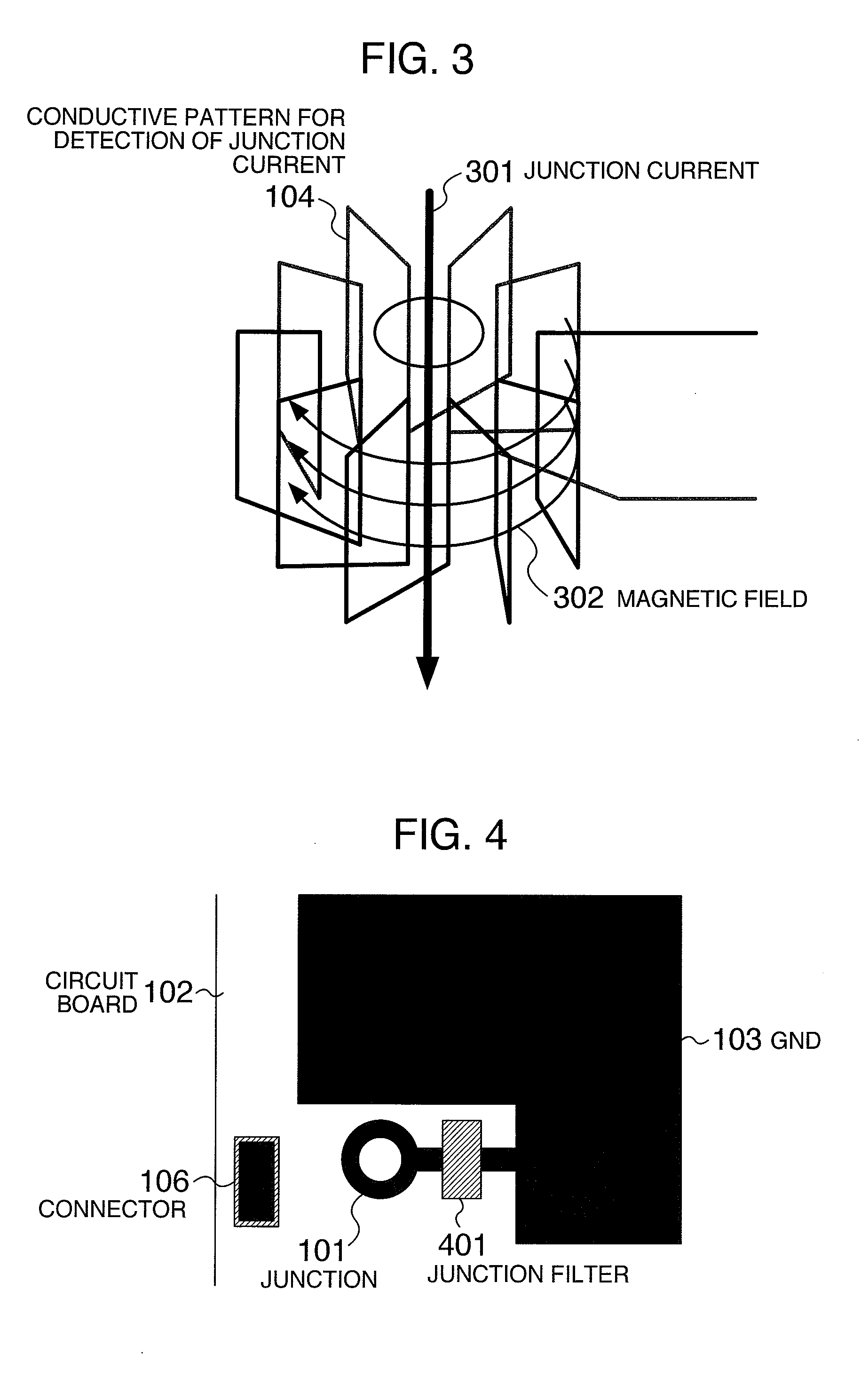
[0028]That is, the circuit board of the invention is characterized in that a sensor, for example, a coil-shaped conductive pattern for detecting an electromagnetic field which is generated by a current flowing in a junction part is provided in a peripheral portion of a through hole for the junction part with the casing or the electronic apparatus. Since the coil-shaped conductive pattern is arranged around the junction part in the circuit board, when the circuit board is mounted in the casing or the like, the electromagnetic field generated by a junction current flowing through the junction part (screw or the like) attached to the junction can be detected in the mounting state and in an actual operating state of the circuit board. Further, since the circuit board has...


PUM


Abstract

A circuit board having: a through hole to mount the circuit board to a casing or an electronic apparatus; and a coil-shaped conductive pattern provided on a plane perpendicular to the through hole so as to intersect a circumference around the through hole as a center.

Description

INCORPORATION BY REFERENCE[0001]The present application claims priority from Japanese application JP2006-058852 filed on Mar. 6, 2006, the content of which is hereby incorporated by reference into this application.BACKGROUND OF THE INVENTION[0002]The invention relates to a circuit board having functions for measuring and adjusting intensity and a phase of a current flowing in a junction of the circuit board and an electronic apparatus or a casing and also relates to an electronic apparatus in which such a circuit board has been mounted.[0003]In an electronic apparatus or the like, in order to specify a position of a current which becomes a cause of generation of an unnecessary electromagnetic radiation and an electromagnetic mutual interference path between electronic apparatuses or electronic circuits which becomes a cause of the erroneous operation, performance deterioration, or the like, a technique for measuring distribution of magnetic fields near the electronic apparatus is ef...

Claims


Application Information

Patent Timeline
IPC IPC(8): H01R12/00
CPCG01R31/001H05K1/0268H05K2201/10969H05K3/429H05K2201/09809H05K1/165
Inventor FUNATO, HIROKISUGA, TAKASHIHARA, TSUTOMU
Owner HITACHI LTD
Learn More