Non-contact power feeding apparatus of magnetic resonance method

a magnetic resonance and non-contact technology, applied in the direction of charging stations, rail devices, transportation and packaging, etc., can solve the problem of too high cost, and achieve the effect of reducing the risk of generating such an electromagnetic disturbance and unnecessary electromagnetic radiation

Inactive Publication Date: 2012-07-05
SHOWA AIRCRAFT INDUSTRY
View PDF6 Cites 14 Cited by
  • Summary
  • Abstract
  • Description
  • Claims
  • Application Information

AI Technical Summary

Benefits of technology

[0060]By providing an insulating transformer in the power feeding side circuit to prevent the flow of the common-mode current, unnecessary electromagnetic radiation is reduced and as a result, the risk of generating such an electromagnetic disturbance can be reduced.
[0061]The present invention has prominent effects in that all the problems of the conventional examples of this kind can be solved by the first, second and third effects.

Problems solved by technology

However, in the conventional non-contact power feeding apparatus 10 of a magnetic resonance method, it has been pointed out that the exciting apparent power for exciting the power transmission coil 3 becomes extremely large, a high-frequency power source 9 of high capacity is required and it costs too much.

Method used


Image

  • Non-contact power feeding apparatus of magnetic resonance method
  • Non-contact power feeding apparatus of magnetic resonance method
  • Non-contact power feeding apparatus of magnetic resonance method

Examples


embodiments

[0141]Embodiments of the present invention will now be described hereunder.

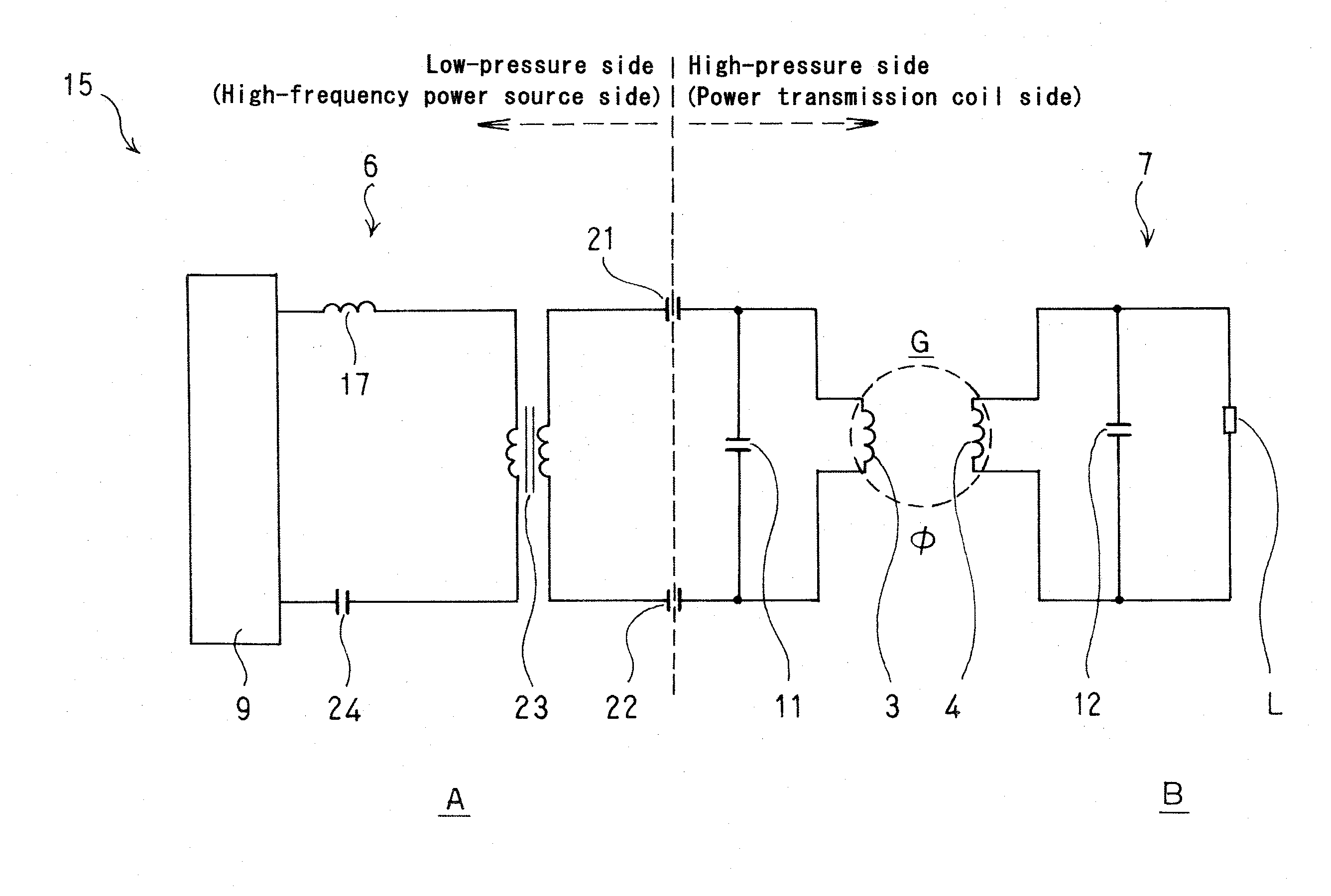
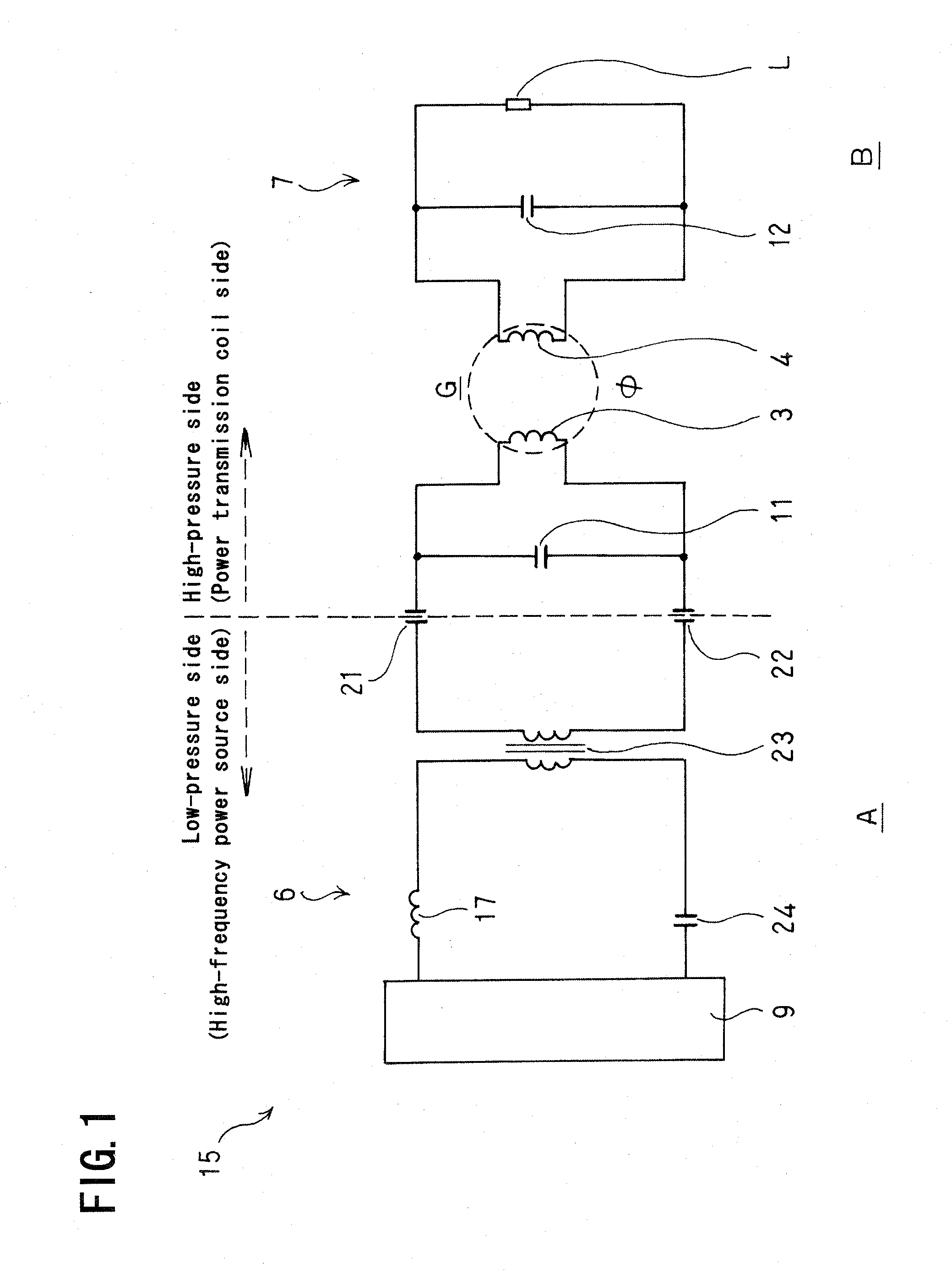
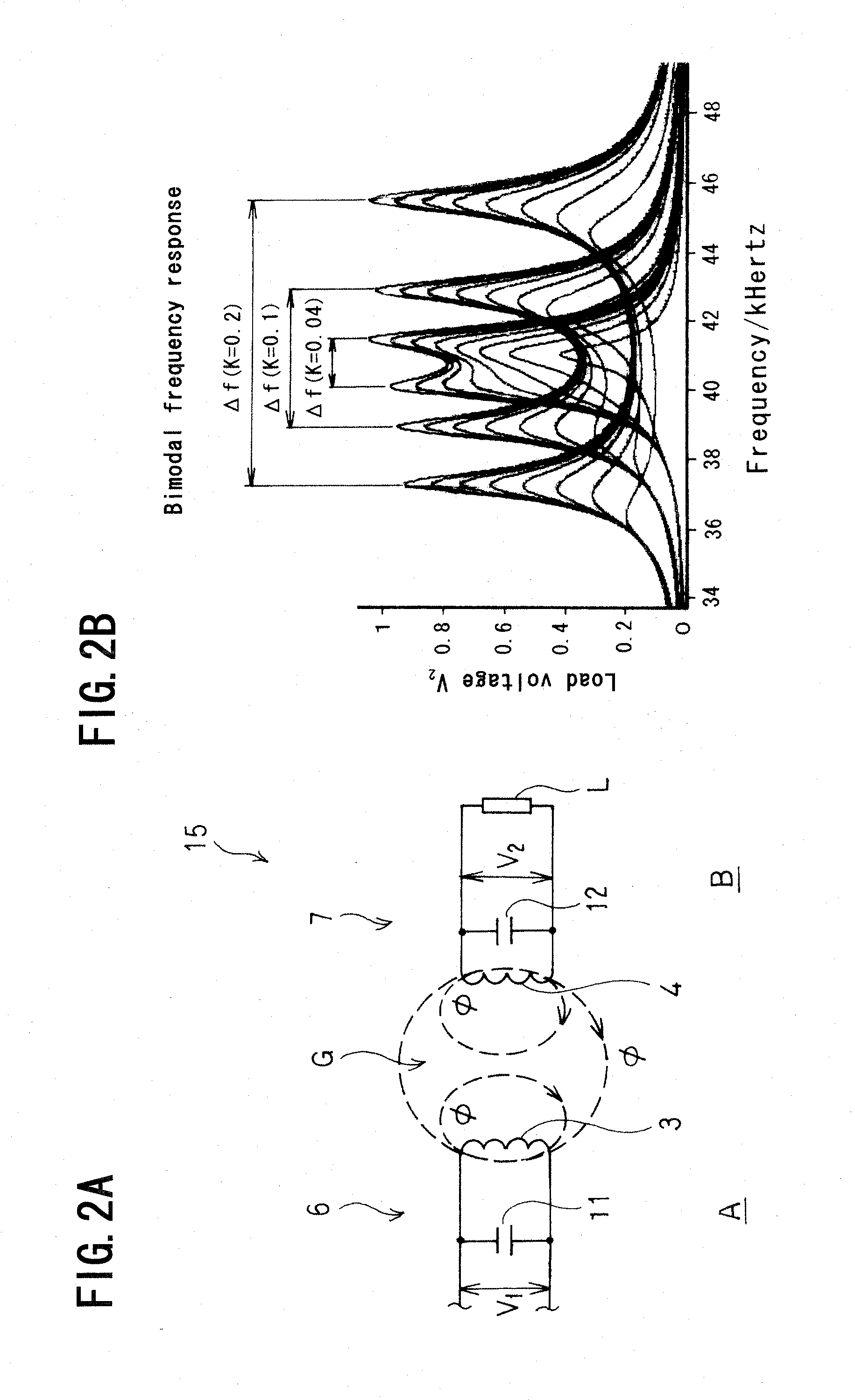
[0142]We run a computer simulation in a case where the non-contact power feeding apparatus 15 of the present invention is implemented in a circuit of FIG. 1 to feed power of about 2 kW to a load L of the power receiving side circuit 7.

[0143]In this case, K-value=0.05, the self-inductance L1 of the power transmission coil 3=26.2 (H), and the self-inductance L2 of the power receiving coil 4=18.2 (H). The capacitance of the parallel capacitor 11=100 n (F), the capacitance of the parallel capacitor 12=170 n (F) and the capacitance of the electric field coupling capacitors 21 and 22=50 n (F) (The capacitance of the electric field coupling capacitors 21 and 22 is not needed to have the same value as shown above).

[0144]As a result of simulation under the conditions described above, the following data was obtained:

High-Frequency Power Source 9:

[0145]

257 V×10 A=(Power) supply power of 2.57 kW

To the Side of a Primary C...


PUM

PropertyMeasurementUnit
output voltageaaaaaaaaaa
poweraaaaaaaaaa
voltageaaaaaaaaaa

Abstract

In this non-contact power feeding apparatus, a power feeding circuit is provided with a power transmission coil and a first parallel capacitor to provide a first parallel resonance circuit, while a power receiving circuit is provided with a power receiving coil and a second parallel capacitor to provide a second parallel resonance circuit. Both parallel resonant circuits are set to have the same resonance frequency and a power frequency of a high-frequency power source in the power feeding side circuit is set to be the same as this resonance frequency. A circuit section including the high-frequency power source and a circuit section including the first parallel capacitor and the power transmission coil are connected by the electric field coupling of electric field coupling capacitors.

Description

BACKGROUND OF THE INVENTION[0001]The present invention relates to a non-contact power feeding apparatus, and more particularly to a non-contact power feeding apparatus of a magnetic resonance method adapted to feed power with no contact from, for example, a power feeding side on the side of a ground surface to a power receiving side on the side of a vehicle.[0002]A non-contact power feeding apparatus adapted to feed power from outside to, for example, a vehicle such as an electric vehicle without any mechanical contact such as a cable has been developed based on the demand and this apparatus is in practical use.[0003]In such a non-contact power feeding apparatus, power is fed from a power transmission coil of a power feeding side circuit fixedly disposed on the ground side to a power receiving coil of a power receiving side circuit mounted on the side of a movable body such as a vehicle, which are closely disposed to face each other, through an air gap of, for example, tens of milli...

Claims


Application Information

Patent Timeline
Patent Type & Authority Applications(United States)
IPC IPC(8): H02J17/00B60L5/00B60M7/00H01F38/14
CPCB60L11/182H02J5/005B60L2200/26Y02T90/14Y02T90/122Y02T10/7005Y02T10/7072B60L53/12Y02T10/70H02J50/50H02J50/12H02J50/70H03H3/0077H03H2003/0414Y02T90/12
Inventor YAMAMOTO, KITAOSATO, TAKESHIABE, KEISUKEMOCHIZUKI, MASASHIOKIYONEDA, YASUYUKI
Owner SHOWA AIRCRAFT INDUSTRY
Why Eureka
Try Eureka