

Elastic cord and pull exerciser having the same
a technology of elastic cord and pull exerciser, which is applied in the field of elastic cord, can solve the problems of troublesome assembly procedures of the sleeve b>32/b>
- Summary
- Abstract
- Description
- Claims
- Application Information
AI Technical Summary
Benefits of technology
Problems solved by technology
Method used
Image

Examples
Embodiment Construction
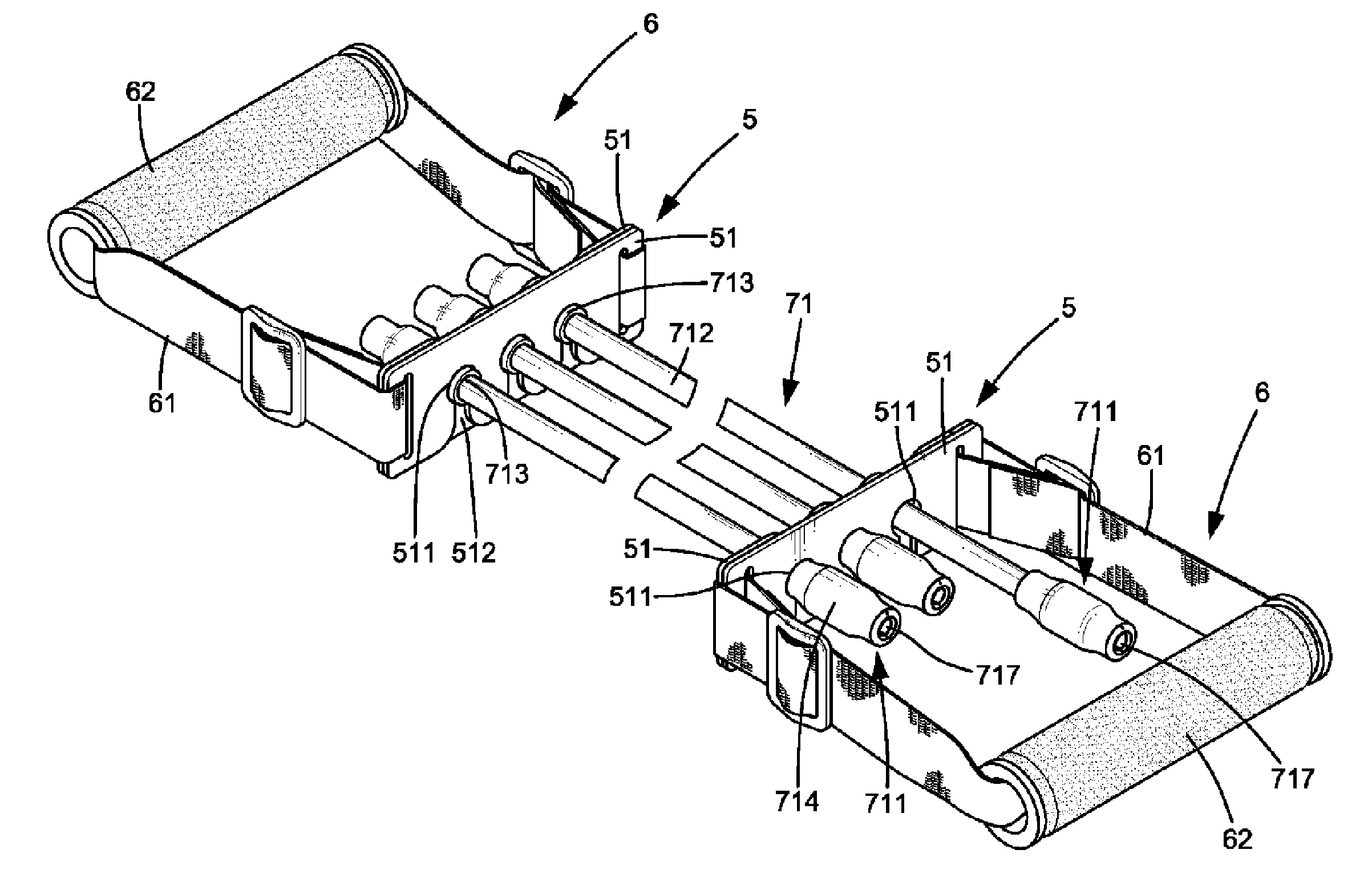
[0019]FIG. 3 is a perspective view of a pull exerciser in accordance with the present invention. FIG. 4 is a sectional view of a portion of the pull exerciser in FIG. 3.
[0020] In this embodiment, the pull exerciser comprises two positioning devices 5, two attachment devices 6, and at least one elastic cord 71 (three in this example). Each attachment device 6 comprises a handle 62 and a length-adjustable belt 61 extending through the handle 62.
[0021] Each positioning device 5 is coupled with an associated attachment device 6 in a position opposite an associated handle 62. Each positioning device 5 includes two positioning plates 51 each having at least one positioning hole 511 (three in this example). Each positioning hole 511 is in communication with outside via a reduced opening 512. An example of the positioning device 5 is disclosed in Applicant's U.S. Pat. No. 6,676,576, the entire contents of which are incorporated herein by reference.
[0022] Each elastic cord 71 is substanti...
PUM
 Abstract
Description
Claims
Application Information