Modular polyaxial pedicle screw assembly with split ring

a polyaxial pedicle screw and module technology, applied in the direction of internal osteosynthesis, internal osteosynthesis, osteosynthesis devices, etc., can solve problems such as poor testing

Active Publication Date: 2022-06-28
CURITEVA INC
View PDF29 Cites 0 Cited by
  • Summary
  • Abstract
  • Description
  • Claims
  • Application Information

AI Technical Summary

Benefits of technology

[0007]The saddle, when placed on the screw head, further prevents the pedicle bone screw from dislodging. The distal end of the tulip has a distal opening for receiving the pedicle screw, the distal opening preferably has a conical surface tapering inwardly from the distal end of the tulip. The outer diameter of the split locking ring is larger than a distal opening of the tulip. The bone screw has one of the following head shapes; at least partially a hemispherical or spherical head, conical or a radial array or loci of cylindrical surfaces or any other bulbous head. The recess, groove or undercut of the tulip has a distal base for supporting the split locking ring. The recess, groove or undercut has an annular wall extending from the distal base to a proximal end of the recess, groove or undercut. The annular wall extends from the distal base a distance (d), the distance (d) being at least equal to or greater than the thickness of the split ring body. The split ring body has an inner diameter having an inner surface wall of a complementary shape to the screw head. The inner surface wall is configured to hold the screw head.

Problems solved by technology

This is not a good test as the assembly can be loosened or the screw to bone interface weakened.

Method used


Image

  • Modular polyaxial pedicle screw assembly with split ring
  • Modular polyaxial pedicle screw assembly with split ring
  • Modular polyaxial pedicle screw assembly with split ring

Examples


second embodiment

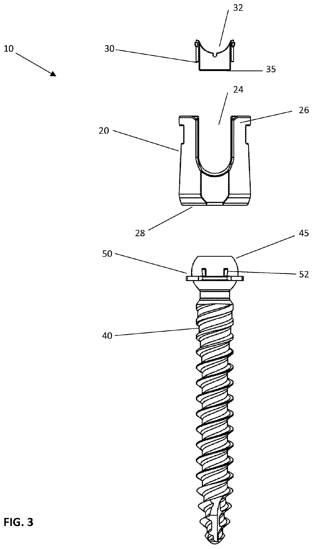
[0033]In a second embodiment illustrated in FIGS. 11 and 12, the split locking ring 50 has all the features previously mentioned, however additional positioning tabs 52 are provided. Accordingly, one or more positioning tabs 52 are provided on each side of the split locking ring 50 near the gap opening 58. This provides six positioning tabs 52 projecting outwardly from the exterior surface and more complimentarily fits the screw head 45 on assembly. This view of FIGS. 11 and 12 shows the positioning of the positioning tabs 52 about the split ring body 51.

third embodiment

[0034]In a third embodiment shown in FIGS. 13 and 14, there are ten positioning tabs 52 positioned about the split locking ring 50 providing even more contact and support for the screw head 45 on assembly and four flexure portions 54 to further facilitate assembly.

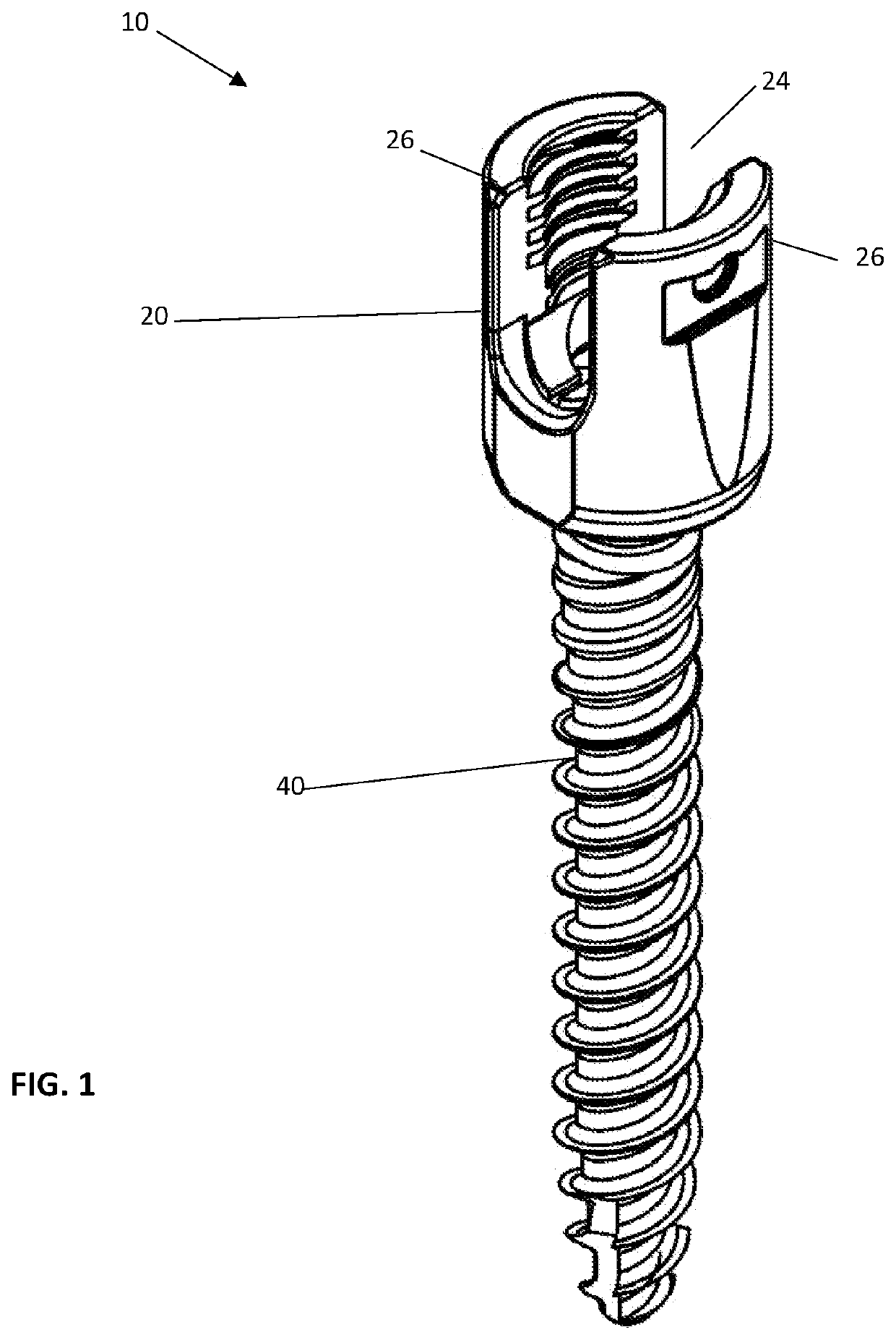
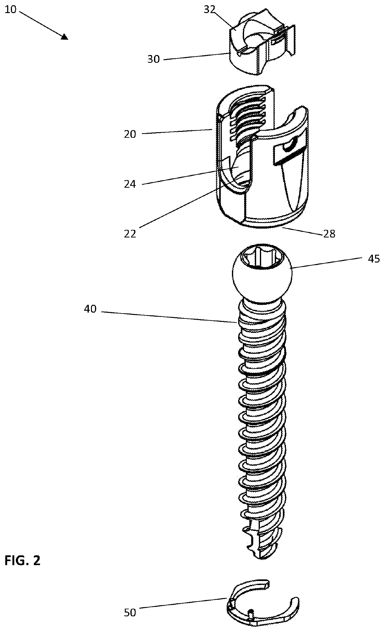
[0035]It is important to note that any of the split locking ring 50 embodiments shown in these views can be used in the assembly views of FIGS. 1-8. Upon assembly of the rod 60 into the tulip 20 tightening the set screw 70 into the tulip presses the rod 60 against the saddle 30 thereby causing the tulip 20 to pull upwardly relative to the saddle 30 which tightens the split locking ring 50 and its associated positioning tabs 52 snugly against the screw head 45. Upon assembly, the screw head 45 is configured to be held only by the split locking ring 50 which in turn is held by the base and the tulip 20. As the tightening occurs, the ability of the polyaxial screw 40 and the tulip 20 to move relative to each other is limited ...


PUM


Abstract

A modular head polyaxial pedicle screw assembly has a pedicle bone screw, a tulip, a split locking ring and a saddle. The screw has a head and a threaded shank. The split locking ring has a split ring body with one or more positioning tabs extending from a first surface of the split ring body. The split ring locking ring is configured to be placed internal of the tulip positioned in a recess, groove or undercut of an inner surface of the tulip. Upon assembly of the pedicle screw into the tulip, at least a maximum diameter of the head is positioned above the recess, groove or undercut allowing the split locking ring to be inserted into the recess or groove thereby securing the pedicle screw inside the tulip wherein the head of the pedicle screw abuts the one or more positioning tabs.

Description

TECHNICAL FIELD[0001]The present invention relates to an improved modular head polyaxial pedicle screw assembly with a split ring.BACKGROUND OF THE INVENTION[0002]Bone anchor screws come in a variety of shapes and sizes. One of the more common styles has a polyaxial head that allows for the screw to enter the bone structure at an ideal or preferred inclination. To achieve this polyaxial inclination, the head has a shape configured to rotate about its lower external surface. This lower surface can be one of a number of shapes like conical or spherical or hemispherical. This ability is often used in devices having a modular head assembly.[0003]The modular head polyaxial pedicle screw assembly generally includes a tulip. A tulip is a body structure having two opposing sides spaced by a slotted opening to receive a spinal rod. The tulip often employs internal threads to receive a rod locking set screw to anchor or fix the rod in the tulip. The lower portion of the tulip has an opening t...

Claims


Application Information

Patent Timeline
Patent Type & Authority Patents(United States)
IPC IPC(8): A61B17/70
CPCA61B17/7032A61B17/7023A61B17/7044A61B17/7035
Inventor LINDER, ERICDAFFINSON, BRION
Owner CURITEVA INC
Why Eureka
Try Eureka