Optical fiber holder and optical fiber cleaving apparatus to which optical fiber holder is attachable

Active Publication Date: 2017-08-17
SEI OPTIFRONTIER CO LTD
View PDF9 Cites 1 Cited by
  • Summary
  • Abstract
  • Description
  • Claims
  • Application Information

AI Technical Summary

Benefits of technology

[0007]According to an embodiment of the present invention, there is provided an optical fiber holder which is configured to hold an optical fiber. The optical fiber holder includes a holder main body, a V-groove which is formed on an upper surface of the holder main body and configured to accommodate a first optical fiber, a recessed groove which is formed on a same straight line with the V-groove at a side closer to a termination portion of an optical fiber than the V-groove and configured to accommodate a second optical fiber, of which a c

Problems solved by technology

However, with the optical fiber holder, positioning of an opt

Method used


Image

  • Optical fiber holder and optical fiber cleaving apparatus to which optical fiber holder is attachable
  • Optical fiber holder and optical fiber cleaving apparatus to which optical fiber holder is attachable
  • Optical fiber holder and optical fiber cleaving apparatus to which optical fiber holder is attachable

Examples


Embodiment Construction

Description on Embodiments

[0037]Embodiments of the present invention will be listed below.

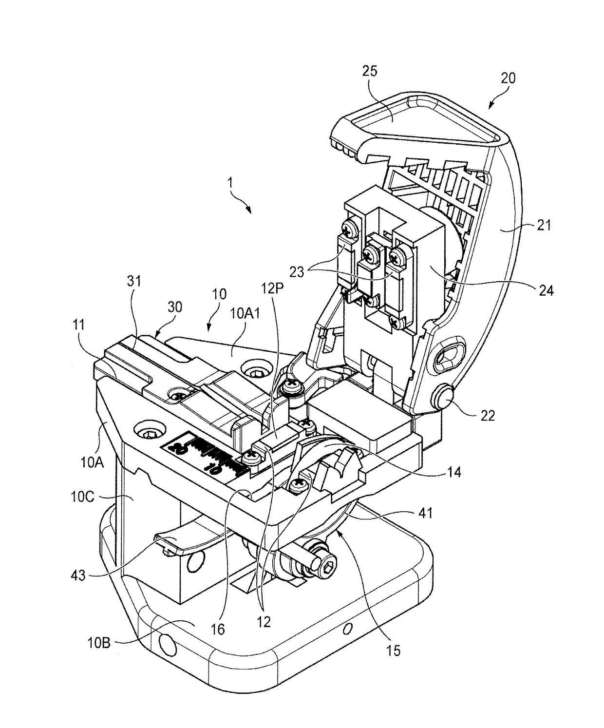
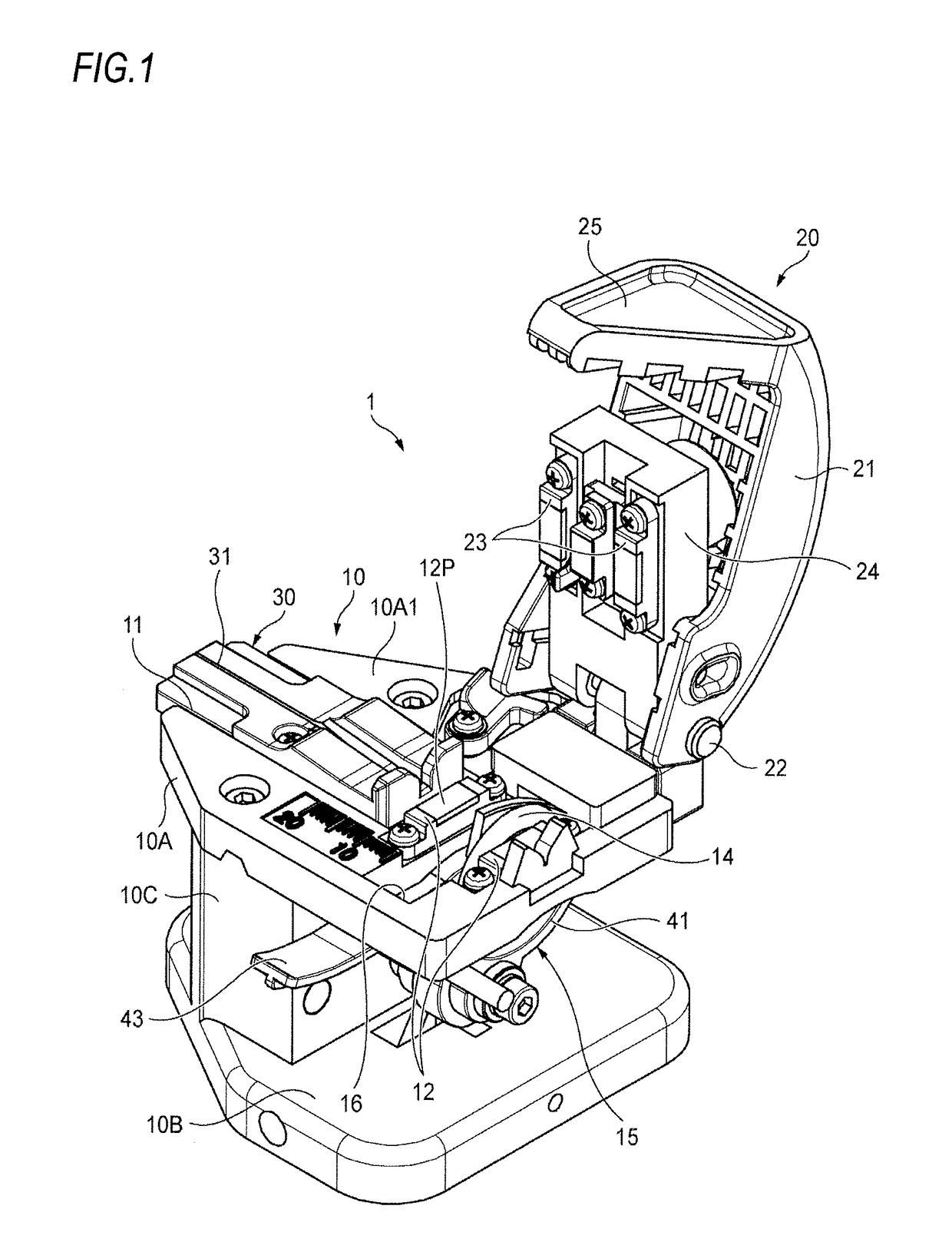
[0038](1) An embodiment of the present invention provides an optical fiber holder which is configured to hold an optical fiber and includes:

[0039]a holder main body;

[0040]a V-groove which is formed on an upper surface of the holder main body and configured to accommodate a first optical fiber;

[0041]a recessed groove which is formed on a same straight line with the V-groove at a side closer to a termination portion of an optical fiber than the V-groove and configured to accommodate a second optical fiber, of which a coating portion has a larger outer diameter than that of the first optical fiber; and

[0042]an abutting portion which is provided on an end portion of the recessed groove on an opposite side to the V-groove and includes an opening portion which has a smaller width than the recessed groove,

[0043]wherein when the second optical fiber is accommodated in the recessed groove, a fiber core ...


PUM


Abstract

An optical fiber holder includes a holder main body, a V-groove which is formed on an upper surface of the holder main body and accommodates a first optical fiber, a recessed groove which is formed on a same straight line with the V-groove and accommodates a second optical fiber having a coating portion with a larger outer diameter than the first optical fiber, and an abutting portion which is provided on an end portion of the recessed groove on an opposite side to the V-groove and includes an opening portion which has a smaller width than the recessed groove. When the second optical fiber is accommodated in the recessed groove, a fiber core wire of the second optical fiber protrudes to an outside via the opening portion and an end portion of the coating portion of the second optical fiber abuts on the abutting portion.

Description

CROSS-REFERENCE TO RELATED APPLICATION[0001]The present application claims the benefit of priority of Japanese Patent Applications No. 2016-025134 filed on Feb. 12, 2016, the content of which is incorporated herein by reference.TECHNICAL FIELD[0002]The present invention relates to an optical fiber holder which holds an optical fiber and an optical fiber cleaving apparatus to which the optical fiber holder is attachable.BACKGROUND ART[0003]JP-A-06-51149 and JP-A-2005-249922 disclose optical fiber holders which hold an optical fiber and are attached to an optical fiber cleaving apparatus or an optical fiber splicing apparatus.[0004]Specifically, JP-A-06-51149 discloses an optical fiber core wire holding apparatus, wherein a holding block formed with a V-shaped groove is accommodated in an accommodation recess of a holding frame body. The optical fiber core wire holding apparatus is used while accommodating a different holding block in the holding frame body depending on the outer diam...

Claims


Application Information

Patent Timeline
IPC IPC(8): G02B6/25
CPCG02B6/25G02B6/3628G02B6/3636G02B6/364
Inventor KURINO, SHINSUKETAKAYANAGI, HIROSHI
Owner SEI OPTIFRONTIER CO LTD
Why Eureka
Try Eureka