Wheelchair suspension

Inactive Publication Date: 2007-09-13
KYMCO
View PDF11 Cites 16 Cited by
  • Summary
  • Abstract
  • Description
  • Claims
  • Application Information

AI Technical Summary

Benefits of technology

[0015] The object of this invention is to provide an electric wheelchair including an improved suspension that increases the elevate

Problems solved by technology

This is a significant amount of time and is indicative of an inferior elevated surface surm

Method used


Image

  • Wheelchair suspension
  • Wheelchair suspension
  • Wheelchair suspension

Examples


Example

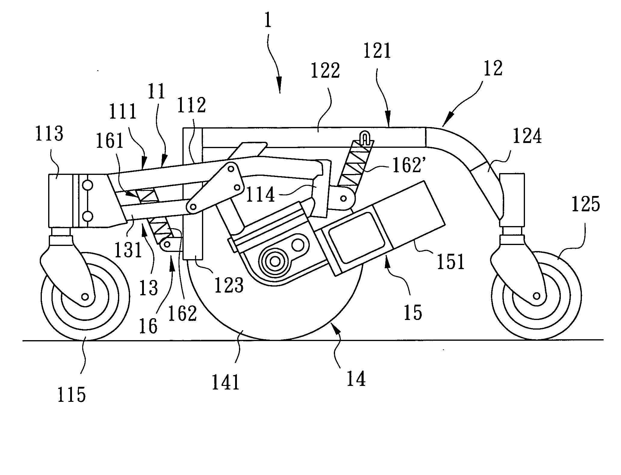
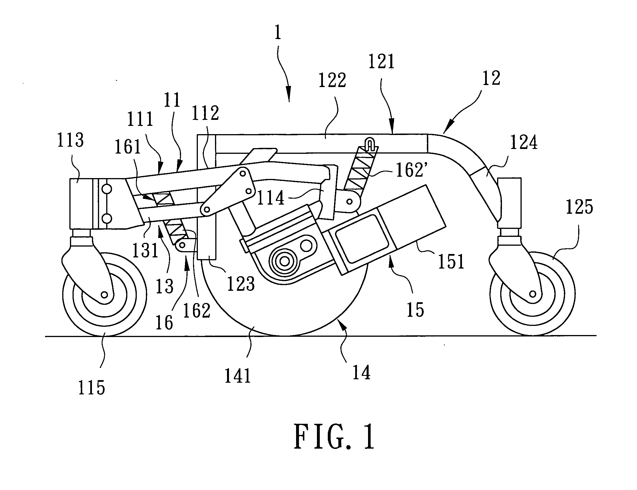
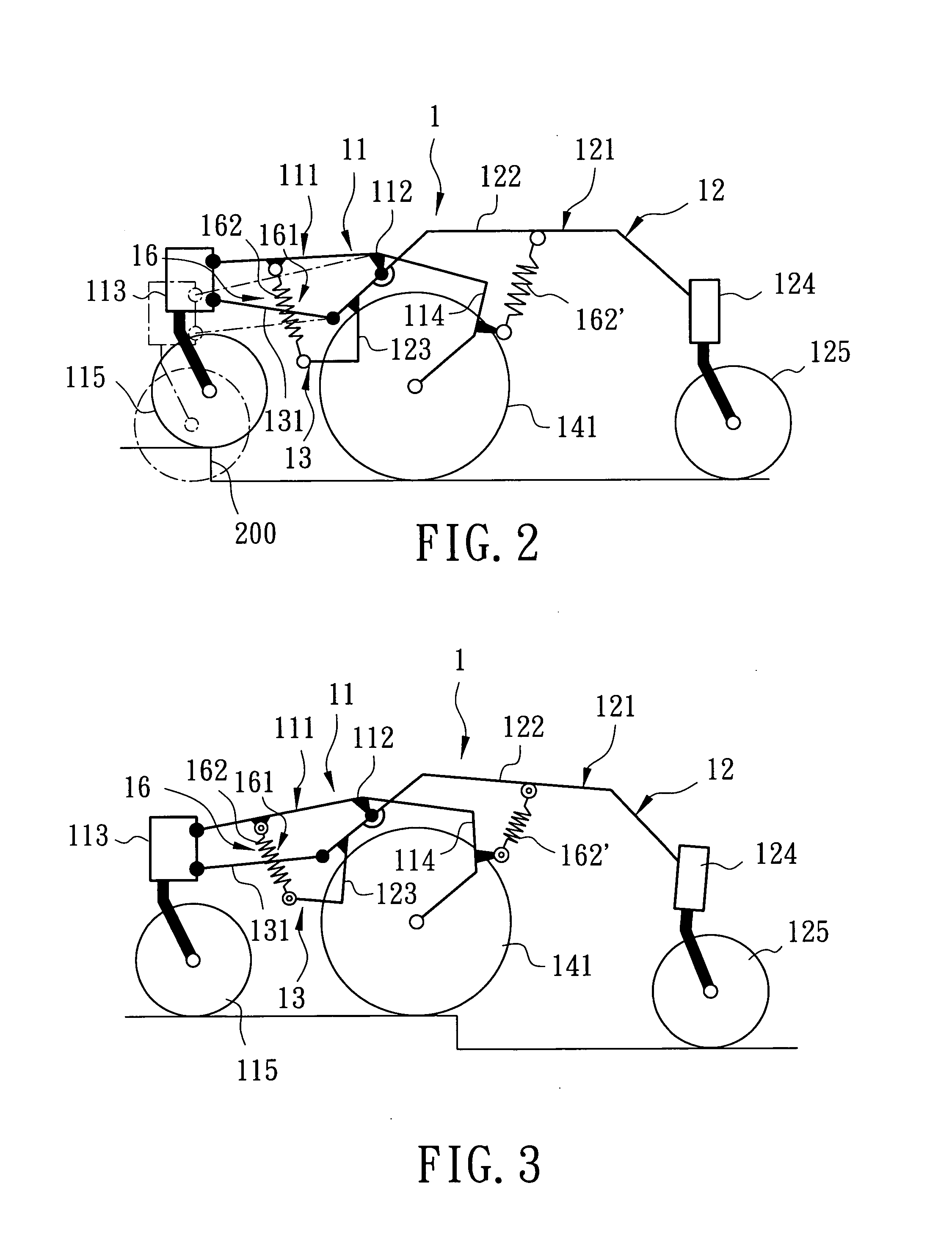
[0027] A wheelchair suspension of this invention is incorporated in an electric wheelchair, and includes two side frame assemblies. Because the two side frame assemblies are similar in construction to each other, the structure and operation of only one side frame assembly will be described.

[0028] Referring to FIG. 5, a side frame assembly 2 of the preferred embodiment of a wheelchair suspension according to this invention includes a generally inverted U-shaped supporting frame unit 21, an upper link unit 22, a lower link unit 23, a drive wheel assembly 24, a connecting frame 25, a first resilient return device 26, a second resilient return device 27, a first caster assembly 28, and a rear caster assembly 29. The first and second resilient return devices 26, 27 are configured as coiled tension springs.

[0029] The supporting frame unit 21 includes a rider-supporting frame 211 for supporting the wheelchair rider, an inclined frame 212 extending integrally, frontwardly, and downwardly ...


PUM


Abstract

A side frame assembly for an electric wheelchair suspension includes a supporting frame unit with a rider-supporting frame, a front caster frame, an upper link having a front end connected pivotally to the front caster frame, and a lower link disposed under the upper link and having a front end connected pivotally to the front caster frame. A drive wheel frame has a front lower end connected pivotally to a pivot portion of the supporting frame unit. A connecting frame has an upper pivot portion connected pivotally to a rear end of the upper link, a lower pivot portion connected pivotally to a rear end of the lower link, and a rear pivot portion connected pivotally to the rear upper end of the drive wheel frame.

Description

BACKGROUND OF THE INVENTION [0001] 1. Field of the Invention [0002] This invention relates to an electric wheelchair, and more particularly to an electric wheelchair suspension. [0003] 2. Description of the Related Art [0004] Referring to FIGS. 1 and 2, a conventional suspension disclosed in U.S. Patent Application Publication No. 2004 / 0060748 A1 is incorporated in an electric wheelchair, and has two side frame assemblies 1, each of which includes a front caster assembly 11, a rear caster assembly 12, a linkage 13, a drive wheel assembly 14, a driving unit 15 and a return spring unit 16. [0005] The front caster assembly 11 includes a front mainframe 112, a front caster frame 113 extending downwardly from a front end of the front mainframe 112, a drive wheel frame 114 extending downwardly from a rear end of the front mainframe 112, and a front caster 115 disposed pivotally on a lower end of the front caster frame 113. [0006] The rear caster assembly 12 includes a rear mainframe 122, ...

Claims


Application Information

Patent Timeline
IPC IPC(8): B60B39/00
CPCB62B5/02B60B33/045Y10S180/907
Inventor CHEN, YUNG-HSINLIAO, YUNG-YUAN
Owner KYMCO
Why Eureka
Try Eureka