Eureka AIR delivers breakthrough ideas for toughest innovation challenges, trusted by R&D personnel around the world.

Fluid spring assembly and method

Inactive Publication Date: 2007-09-13
FIRESTONE IND PROD COMPANY
View PDF6 Cites 3 Cited by
  • Summary
  • Abstract
  • Description
  • Claims
  • Application Information

AI Technical Summary

Benefits of technology

[0007] A fluid spring assembly in accordance with one exemplary embodiment of the present novel concept is provided that includes a first end member and a second end member spaced from the first end member. The second end member includes a first end wall and an opening extending through the first end wall. A flexible sleeve that includes an axis and a sleeve wall extends between first and second open ends. The sleeve wall toward the first open end thereof is secured on the first end member. The sleeve wall toward the second open end thereof is disposed along the first end wall of the second end member. A third end member is supported on the second end member along the first end wall with at least a portion of the sleeve wall toward the second open end thereof disposed between the third end member and the first end wall of the second end member. A retainer extends into the opening and is displaceable therealong. The retainer secures the third end member on the second end member such that the third end member and the sleeve wall can be axially displaced to disengage the third end member and the sleeve wall from the second end member thereby permitting relative rotational movement therebetween.

Problems solved by technology

This can lead to inefficiencies and increased costs and / or inventory levels where a variety of mounting configurations of a given model of fluid spring assembly are requested and / or used.
One difficulty with such an approach, however, is that known fluid spring assemblies typically require some amount of disassembly to make the adjustments.
Additionally, significant time and effort are often required to reconfigure a quantity of fluid spring assemblies.
This undesirably increases the costs associated with the use of such fluid spring assemblies.

Method used


Image

  • Fluid spring assembly and method
  • Fluid spring assembly and method
  • Fluid spring assembly and method

Examples


Embodiment Construction

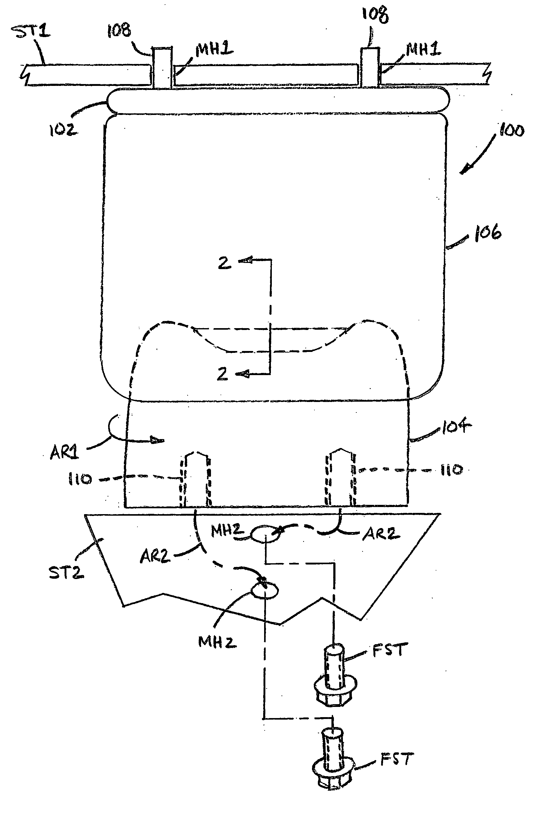
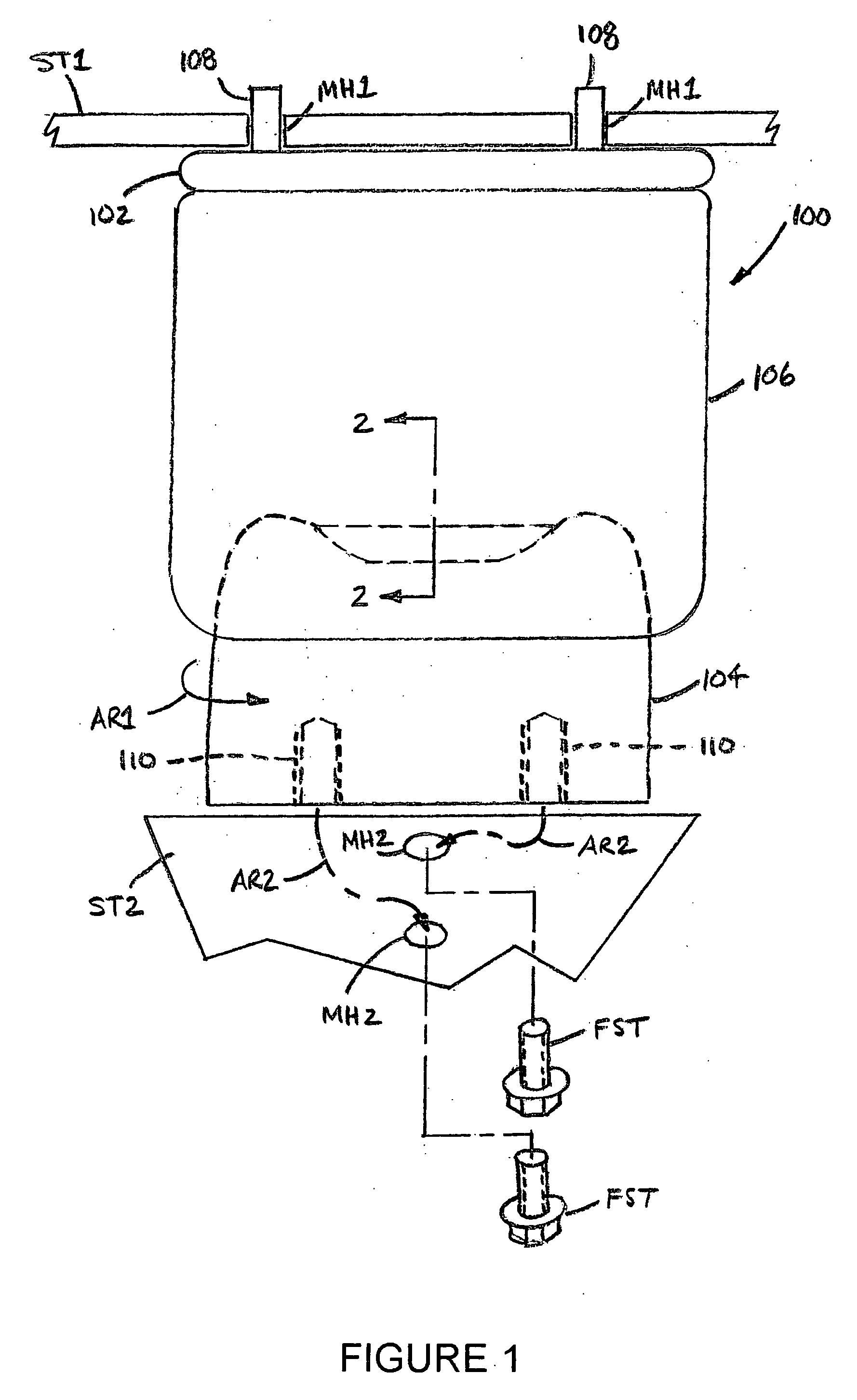
[0013] Referring now in greater detail to the drawings, wherein the showings are for the purposes of illustrating exemplary embodiments of the subject novel concept only, and not for the purpose of limiting the same, FIG. 1 illustrates a fluid spring assembly 100 supported between associated structural components ST1 and ST2, such as a body or frame and a wheel-engaging member of an associated vehicle, for example. The associated structural components include mounting portions having suitable features for mounting or otherwise securing a fluid spring assembly thereon. As an example of suitable mounting features, mounting holes MH1 are provided on associated structural component ST1 and mounting holes MH2 are provided on associated structural component ST2. It will be recognized that mounting holes MH1 and MH2 are disposed at two different orientations with mounting holes MH1 being spaced apart across the drawing figure and mounting holes MH2 being spaced apart along the length of th...


PUM


Abstract

A fluid spring assembly includes a first end member and a second end member spaced from the first end member. A spring sleeve extends between the first and second end members. A third end member is disposed along the second end member and is axially displaceably secured thereto. The third end member engages the spring sleeve and is displaceable between a fully-assembled use condition and a fully-assembled adjustment condition in which the third end member and spring sleeve are disassociated with the second end member permitting approximately free rotation thereof. A method includes adjusting the rotational alignment of the fluid spring assembly.

Description

BACKGROUND [0001] The present disclosure broadly relates to the art of spring devices and, more particularly, to a fluid spring assembly having end members that can be quickly and easily repositioned relative to one another without the use of tools or instruments, as well as a method of adjusting the same. [0002] The present novel concept finds particular application and use in association with vehicle suspension systems and will be shown and described herein with specific reference thereto. However, it is to be understood that the present novel concept is capable of broad use in a wide variety of applications and environments, such as machinery mounting applications, for example. As such, reference herein to specific applications and / or uses is merely exemplary and is not intended to be limiting. [0003] Fluid spring assemblies using a compressed gas medium, such as air, for example, are well known and commonly used as components of vehicle suspension systems, as an example of one o...

Claims


Application Information

Patent Timeline
IPC IPC(8): B60G11/27
CPCB60G11/27B60G11/28F16F9/057B60G2206/424B60G2206/91B60G2204/126
Inventor LEVY, DANIEL I.
Owner FIRESTONE IND PROD COMPANY
Why Eureka
Eureka Blog
Learn More