Apparatus for and method of capturing radiation image

a radiation image and apparatus technology, applied in the field of apparatus for and apparatus for capturing radiation images, can solve the problem of inability to detect excessive radiation dosage, and achieve the effect of preventing excessive radiation from being used on the subj

Inactive Publication Date: 2007-09-13
FUJIFILM CORP
View PDF2 Cites 14 Cited by
  • Summary
  • Abstract
  • Description
  • Claims
  • Application Information

AI Technical Summary

Benefits of technology

The technical effect of this patent is that it provides a way to capture a person's body without giving them too much harmful radiation exposure during the process.

Problems solved by technology

This patent discusses how traditional X-ray imaging devices work and how they use various factors to determine the optimal settings for getting a clear image without overexposing the patient. However, this can lead to issues when certain objects, like implants, are present in the patient's body. In these cases, the device may fail to accurately measure the level of radiation passing through the patient and could potentially expose them to too much radiation. The technical problem addressed in this patent is finding ways to ensure accurate detection of necessary radiation levels despite the presence of implants or other obstacles in the patient's body.

Method used


Image

  • Apparatus for and method of capturing radiation image
  • Apparatus for and method of capturing radiation image
  • Apparatus for and method of capturing radiation image

Examples


Embodiment Construction

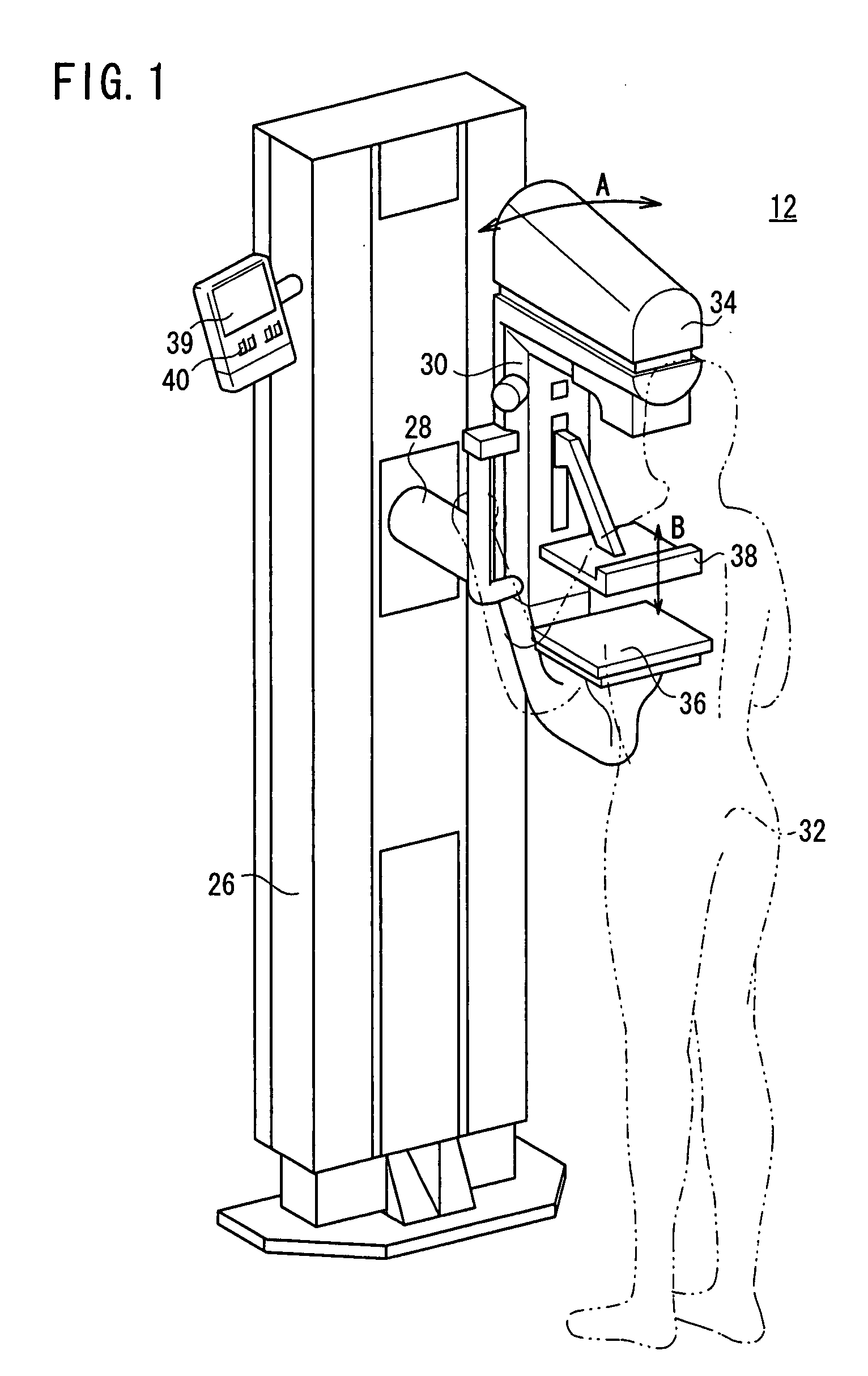
[0021]FIG. 1 shows in perspective a mammographic system 12 to which an apparatus for and method of capturing a radiation image according to an embodiment of the present invention are applied.

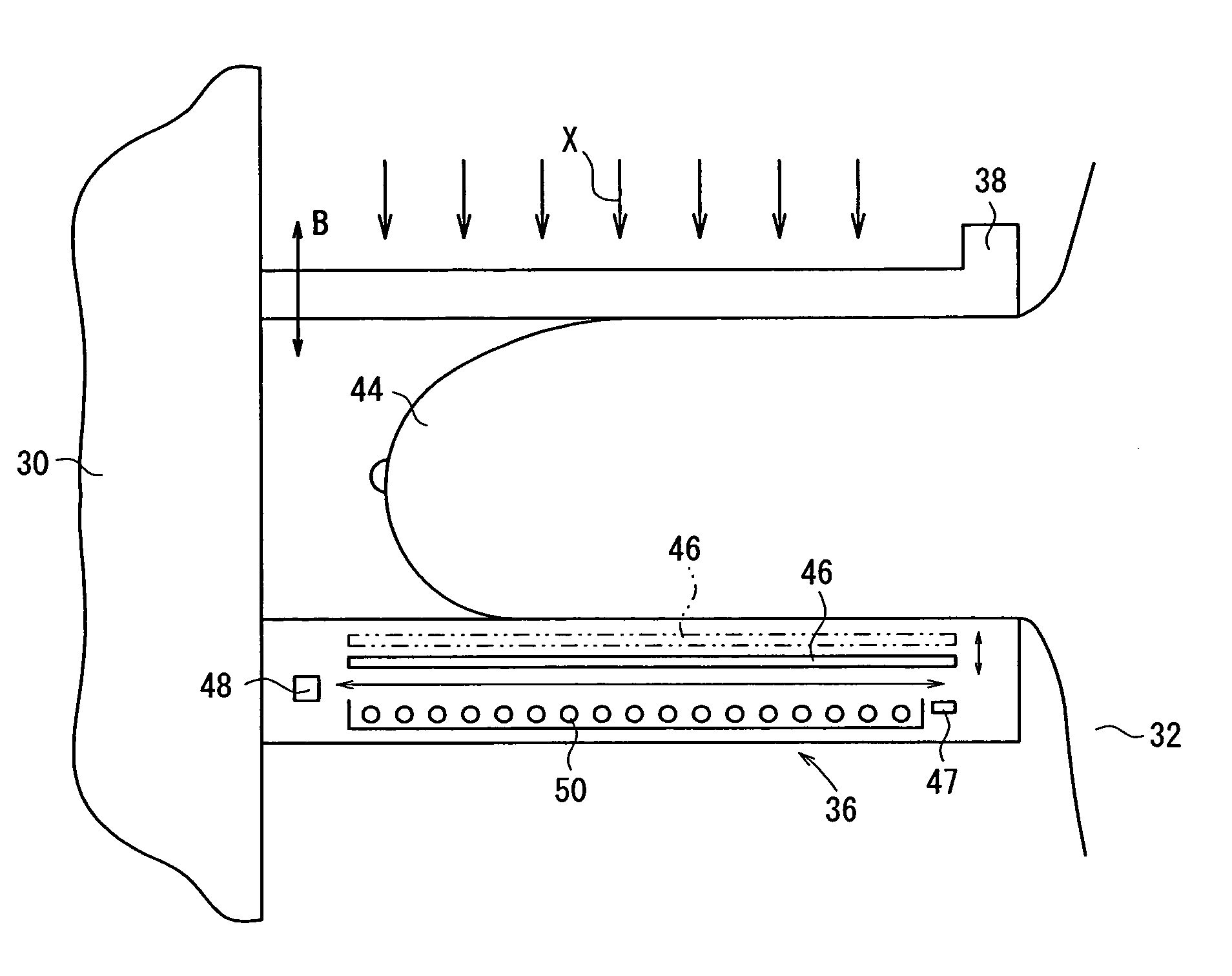
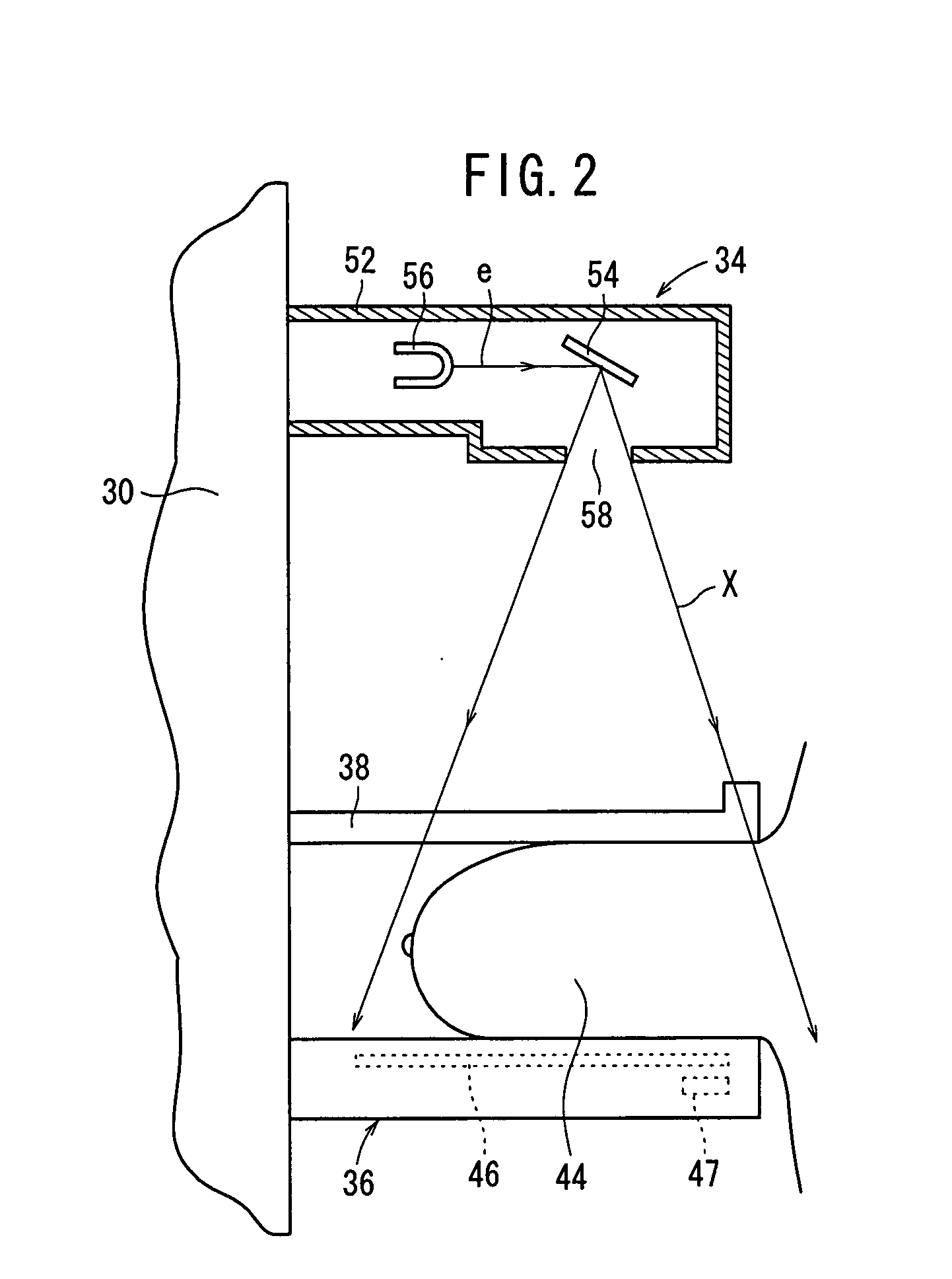
[0022]As shown in FIG. 1, the mammographic system 12 has an upstanding base 26, a vertical arm 30 fixed to a horizontal swing shaft 28 disposed substantially centrally on the base 26, a radiation source housing unit 34 storing a radiation source for applying a radiation to a subject 32 and which is fixed to an upper end of the arm 30, an image capturing base 36 housing a solid-state detector for detecting radiation that has passed through the subject 32 and which is fixed to a lower end of the arm 30, and a presser plate 38 for pressing and holding the subject's breast against the image capturing base 36.

[0023]When the arm 30, to which the radiation source housing unit 34 and the image capturing base 36 are secured, is angularly moved about the swing shaft 28 in a direction indicated by the arro...


PUM


Abstract

A radiation application time upper limit calculator calculates a radiation application time upper limit based on a subject thickness, as measured by a subject thickness measuring unit. While an X-ray tube is controlled according to exposure conditions that have been set in order to apply a radiation X to a breast to capture a radiation image thereof, an X-ray tube controller compares the applied radiation time with the radiation application time upper limit. If the applied radiation time exceeds the radiation application time upper limit, then application of radiation to the subject is interrupted, so as to prevent an inappropriate radiation dosage from being applied to an X-ray detector.

Description


Claims


Application Information

Patent Timeline
Owner FUJIFILM CORP
Why Eureka
Try Eureka