Heating apparatus and induction heating control method

a technology of induction heating and heating control, which is applied in the direction of electric/magnetic/electromagnetic heating, instruments, electrographic processes, etc., can solve the problems of increasing the cost of the whole device, increasing the cost, and increasing the cos

Inactive Publication Date: 2007-09-13
KK TOSHIBA +1
View PDF14 Cites 40 Cited by
  • Summary
  • Abstract
  • Description
  • Claims
  • Application Information

AI Technical Summary

Problems solved by technology

In a case where the plurality of coils are utilized, cost might increase as compared with a case where one coil is utilized.
In this case, circuits to drive the plurality of coils must be prepared in accordance with the number of the coils, which leads to the cost increase, and in addition, there rises a problem that the whole device is enlarged.
In this case, since the driving circuit for supplying the power to the coil is not matched with the heating roller, it becomes difficult to heat an only area that passes the sheet.

Method used


Image

  • Heating apparatus and induction heating control method
  • Heating apparatus and induction heating control method
  • Heating apparatus and induction heating control method

Examples


first embodiment

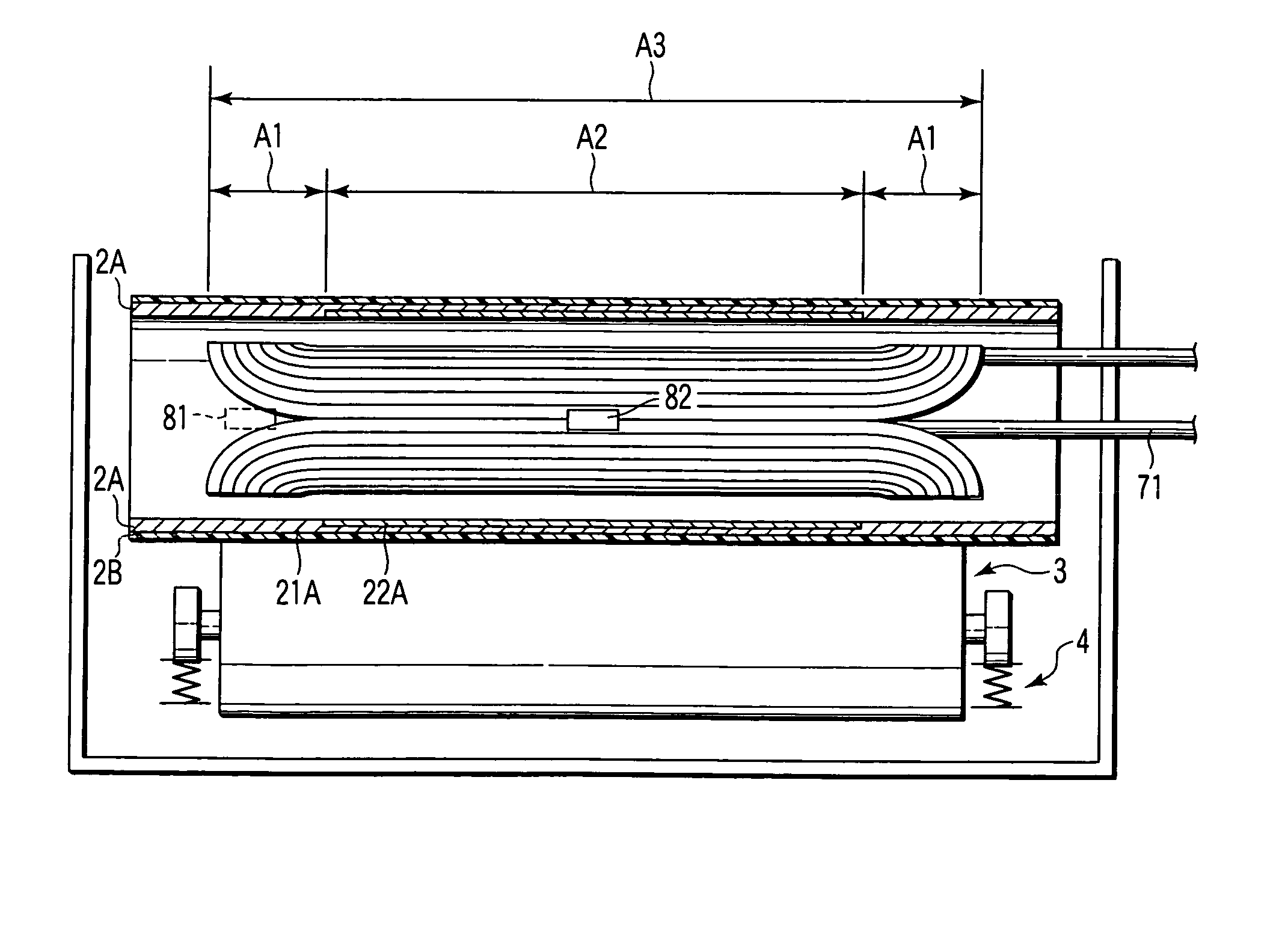
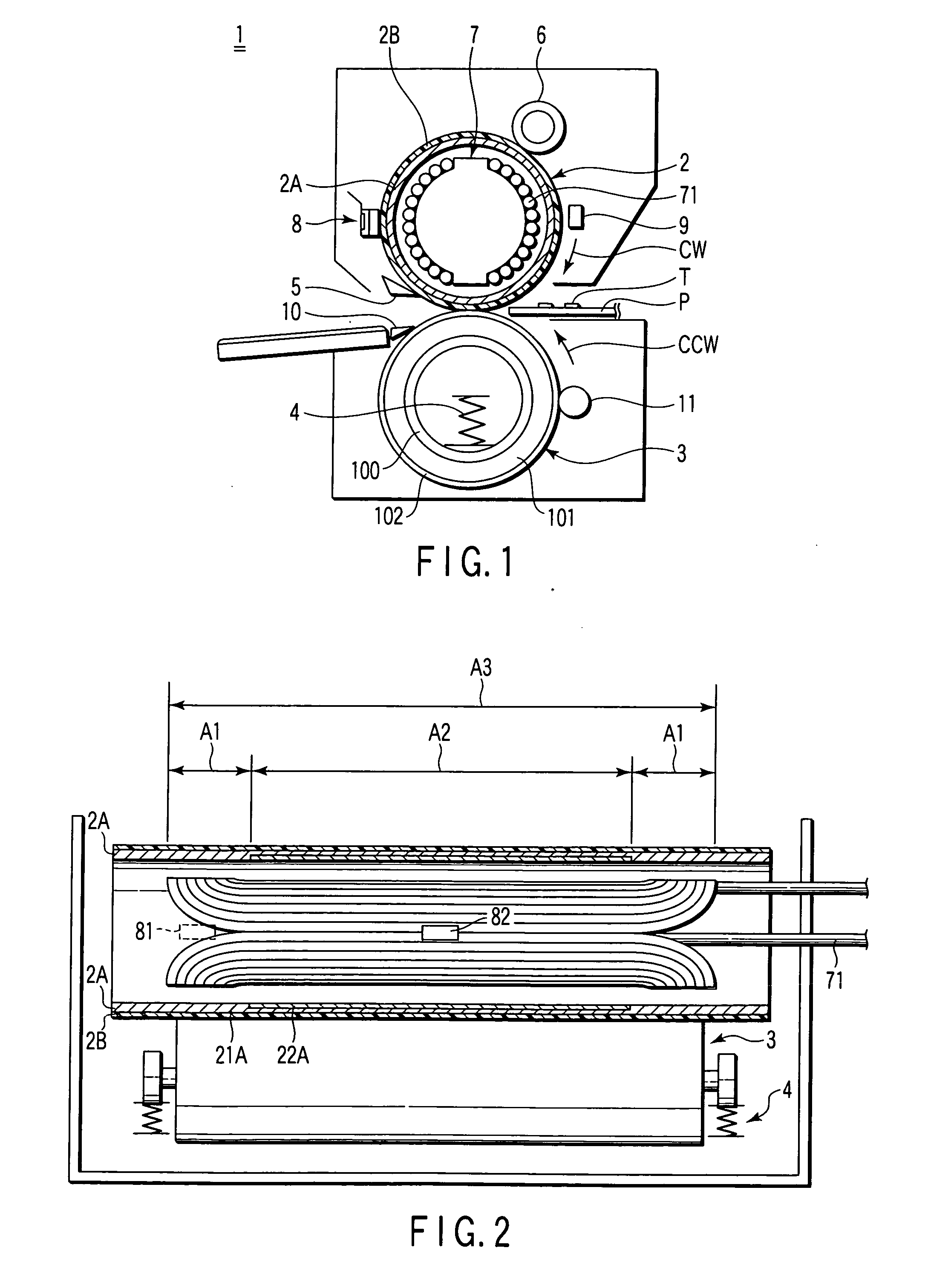
[0044]FIG. 1 shows one example of a fixing device to which an embodiment of this invention is applied. FIG. 2 is a schematic diagram of the fixing device shown in FIG. 1 as viewed from a different direction.

[0045] As shown in FIG. 1, a fixing device 1 has a heating member (heating roller) 2, a pressurizing member (pressurizing roller) 3, a pressurizing spring 4, a peeling claw 5, a cleaning roller 6, an induction heating unit 7, a temperature detecting section 8, and a thermostat 9.

[0046] The heating roller 2 includes a rolled conductive layer 2A constituted by forming a conductive material into a cylindrical shape, and a coating layer (mold-releasing layer) 2B disposed on an outer peripheral surface of this conductive layer 2A and made of a fluorine resin such as an ethylene tetrafluoride resin. This heating roller 2 has a 20 μm thick mold-releasing layer formed on the surface of the conductive layer 2A having a diameter of 40 mm and a thickness of 1 mm.

[0047] The pressurizing r...

second embodiment

[0095] Next, there will be another example of the first embodiment with reference to FIGS. 5 and 6. FIG. 5 shows an example of a fixing device to which the present embodiment is applicable. FIG. 6 shows a schematic diagram of the fixing device shown in FIG. 5 as viewed from a different direction. It is to be noted that components having the same constitutions and functions as those of components shown in FIGS. 1 to 4 are denoted with the same reference numerals, and detailed description thereof is omitted.

[0096] As shown in FIG. 5, a fixing device 100 has a heating roller 200, an induction heating unit 700, a pressurizing roller 3, a pressurizing spring 4, a peeling claw 5, a cleaning roller 6, a temperature detecting section 8, and a thermostat 9.

[0097] The heating roller 200 has: a shaft 200a made of a material having a rigidity (hardness) such that the material does not deform under a predetermined pressure; an elastic layer (a foam rubber layer, a sponge layer, and a silicon r...

third embodiment

[0104] Next, there will be described another example of a first embodiment with reference to FIGS. 7, 8A, and 8B. FIG. 7 shows an example of a fixing device to which the present embodiment is applicable. FIGS. 8A and 8B show schematic diagrams of a heating roller 220 which is applicable to the fixing device shown in FIG. 7.

[0105] As shown in FIG. 7, a fixing device 120 includes: a fixing belt 12; the heating roller 220; a pressurizing roller 321; a fixing roller 322; and an induction heating unit 720.

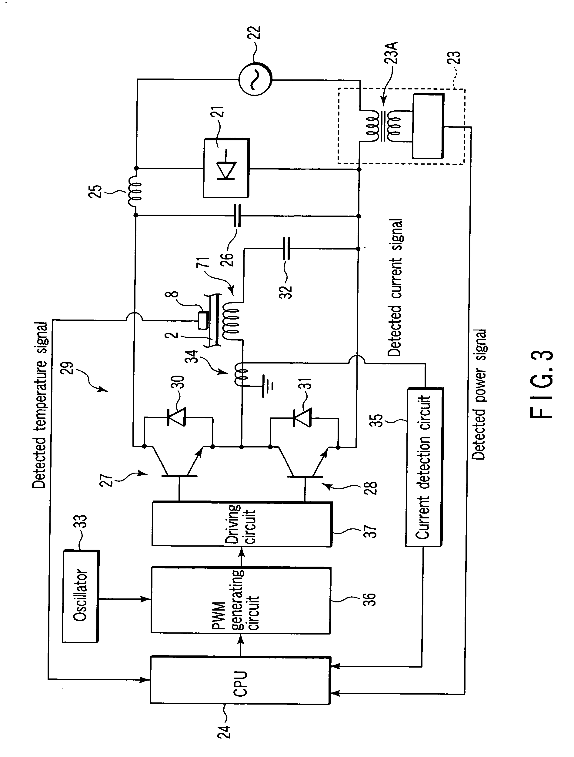
[0106] The induction heating unit 720 is disposed externally along the heating roller 220, and the fixing belt 12 is sandwiched between the induction heating unit and the heating roller 220. The induction heating unit is connected to an induction heating control circuit described above with reference to FIG. 3, and includes: an exciting coil 721 to which a predetermined power is supplied and which supplies a predetermined magnetic field to the heating roller 220; and a magnetic core 7...


PUM


Abstract

In an aspect of this invention, a fixing device includes a heating member including a first area and a second area formed of conductive members (e.g., aluminum and iron) having different magnetic permeability ratios, and an induction heating unit which generates a magnetic field from a coil to induction-heat this heating member, and the fixing device changes a frequency of a high-frequency current to be supplied to the coil to thereby control a heating area of the heating member.

Description

1. FIELD OF THE INVENTION [0001] The present invention relates to a fixing device which is mounted on an image forming device, a copying machine, a printer or the like to form an image on a transfer material by use of an electrophotographic process and which fixes, to the transfer material, a developer on the transfer material. BACKGROUND OF THE INVENTION [0002] In a copying machine or a printer using an electronic process, it is known that a toner image formed on a photosensitive drum is transferred to a transfer member, and thereafter the melted toner image by a fixing device including a heating roller and a pressurizing roller is fixed to the transfer member. [0003] Furthermore, an induction heating system is known in which, in the above case, the surface of the heating roller is heated using a plurality of coils. In a case where the plurality of coils are utilized, cost might increase as compared with a case where one coil is utilized. In this case, circuits to drive the plurali...

Claims


Application Information

Patent Timeline
Patent Type & Authority Applications(United States)
IPC IPC(8): G03G15/20
CPCG03G15/2053G03G2215/2032
Inventor KINOUCHI, SATOSHITAKAGI, OSAMUTSUEDA, YOSHINORISONE, TOSHIHIRO
Owner KK TOSHIBA
Why Eureka
Try Eureka