
Clutch Device for Automatic Speed Changer

Inactive Publication Date: 2007-09-20
TOYOTA JIDOSHA KK
View PDF3 Cites 0 Cited by
  • Summary
  • Abstract
  • Description
  • Claims
  • Application Information

AI Technical Summary

Benefits of technology

[0010] According to the second aspect of the invention, since the connecting part of the rotary shaft and the inner drum portion, and that of the inner drum portion and the outer drum portion can be simultaneously welded, the cost for welding can be reduced.
[0016] According to the fifth aspect of the invention, the lip seal fixed on the outer drum portion seals a space defined by the first piston and the outer drum portion. On the other hand, as Patent Document 1 discloses, in the case that an O-ring is employed for sealing a space defined by the first piston and the outer drum portion, a thick portion for receiving the O-ring is required and, therefore, the axial dimension must be long due to the thick portion. In the case of the fifth aspect of the invention, since such a thick portion is not required, the axial dimension of the outer drum portion can be shorter. Accordingly, the clutch device can be a smaller-size one.

Problems solved by technology

As a result, it causes a disadvantage of providing a substantially large clutch device, namely, a disadvantage that it cannot provide a substantially small clutch device.

Method used


Image

  • Clutch Device for Automatic Speed Changer
  • Clutch Device for Automatic Speed Changer
  • Clutch Device for Automatic Speed Changer

Examples


Embodiment Construction

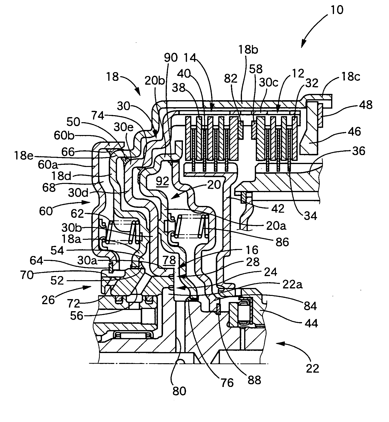
[0047] Hereinafter, there will be described the present invention by reference to the drawings. FIG. 1 is a sectional view showing a part of an automatic transmission for a vehicle including a clutch device 10 constructed according to the present invention, in more detail, the upper half part divided by the axis which is represented by an alternate long and short dashed line.

[0048] The clutch device 10 includes a clutch drum 16 supporting first frictional coupling elements 12 and second frictional coupling elements 14, a first piston 18 disposed radially outwardly of the clutch drum 16 which has a cylindrical shape with a bottom so as to cover the clutch drum 16, and a second piston 20 disposed radially inwardly of the clutch drum 16. The second frictional coupling elements 14 are disposed apart from the first frictional coupling elements 12 in a predetermined distance in the axial direction.

[0049] The clutch drum 16 includes an inner drum portion 26 and an outer drum 30. The inne...


PUM


Abstract

A clutch device for an automatic transmission includes a clutch drum, first and second frictional coupling elements, both supported by the clutch drum, a first piston axially movably disposed radially outwardly of the clutch drum and operating to couple the first frictional coupling elements, and a second piston axially movably disposed radially inwardly of the clutch drum and operating to couple the second frictional coupling elements. The clutch drum includes an inner drum portion welded on a rotary shaft, and an outer drum portion welded on the inner drum portion and supporting the first and second frictional coupling elements. The first piston is axially slidable relative to the inner drum portion. The second piston is axially slidable relative to the rotary shaft. And, a welded portion of the rotary shaft and the inner drum portion, and a welded portion of the inner drum portion and the outer drum portion, are radially spaced in a predetermined distance and concentric with each other.

Description

TECHNICAL FIELD [0001] The present invention relates to a clutch device for an automatic transmission, especially, to the art for providing the small-size clutch device. RELATED ART [0002] There is known a clutch device having an arrangement in which a pair of a group of frictional coupling elements is supported by one clutch drum. That is, it is such a clutch device having a piston disposed radially inwardly of the clutch drum to couple a group of frictional coupling elements and another piston disposed radially outwardly of the clutch drum to couple another group of frictional coupling elements, namely, the clutch device having, what is called, a “pull piston”. [0003] Patent Document 1, JP 2003-106341 A, for example, discloses such a clutch device for the automatic transmission. [0004] In the clutch device of the automatic transmission disclosed in Patent Document 1, the radially outward piston is the “pull piston”, and one of the pair of groups of frictional coupling elements is ...

Claims


Application Information

Patent Timeline
IPC IPC(8): F16D25/10F16D25/0638
CPCF16D25/0638F16D25/10F16D25/12
Inventor ONISHI, HIROFUMIYASUDA, YUJI
Owner TOYOTA JIDOSHA KK
Features
  • Generate Ideas
  • Intellectual Property
  • Life Sciences
  • Materials
  • Tech Scout
  • Unparalleled Data Quality
  • Higher Quality Content
  • 60% Fewer Hallucinations
Learn More