
Workpiece removal device for a hole saw

Active Publication Date: 2006-02-21
EAZYPOWER CORP
View PDF21 Cites 22 Cited by
  • Summary
  • Abstract
  • Description
  • Claims
  • Application Information

AI Technical Summary

Benefits of technology

[0010]Yet another object of the present invention is to direct a spring biasing force perpendicular to a preselected portion of a workpiece. A feature of the device is the integral joining of the first and second securing members with corresponding ends of the biasing spring, the securing members each having an aperture through a central portion thereby forming a “spool” configuration when opposing ends of the biasing spring are joined to the securing members. An advantage of the device is that the relative position of the spring can be maintained while the spring is compressed during the cutting of the predetermined portion of the workpiece. Another advantage of the device is that the relative position of the spring can be maintained when the spring expands and forcibly removes the cut portion of the workpiece from the internal cavity of the hole saw.
[0016]Another object of the present invention is to provide a device that maintains a cut portion of a workpiece within a cavity in the hole saw. A feature of the device is a hole saw having an axial dimension slight shorter than the axial dimension of a drill bit, and relatively longer than the axial dimension of the combined biasing spring and securing members. An advantage of the device is that a severed portion of the workpiece remains partially in the hole saw after removing the hole saw from the workpiece thereby preventing the severed portion from slipping off the drill bit and remaining inside the workpiece.

Problems solved by technology

The problem with prior art hole saws is that the severed portion inside the hole saw can be difficult to remove.
Whatever the technique utilized to remove the severed portion, an excessive loss of time and money result from the user having to wrestle with the manual removal of the severed portion from the hole saw cavity.

Method used


Image

  • Workpiece removal device for a hole saw
  • Workpiece removal device for a hole saw
  • Workpiece removal device for a hole saw

Examples


Embodiment Construction

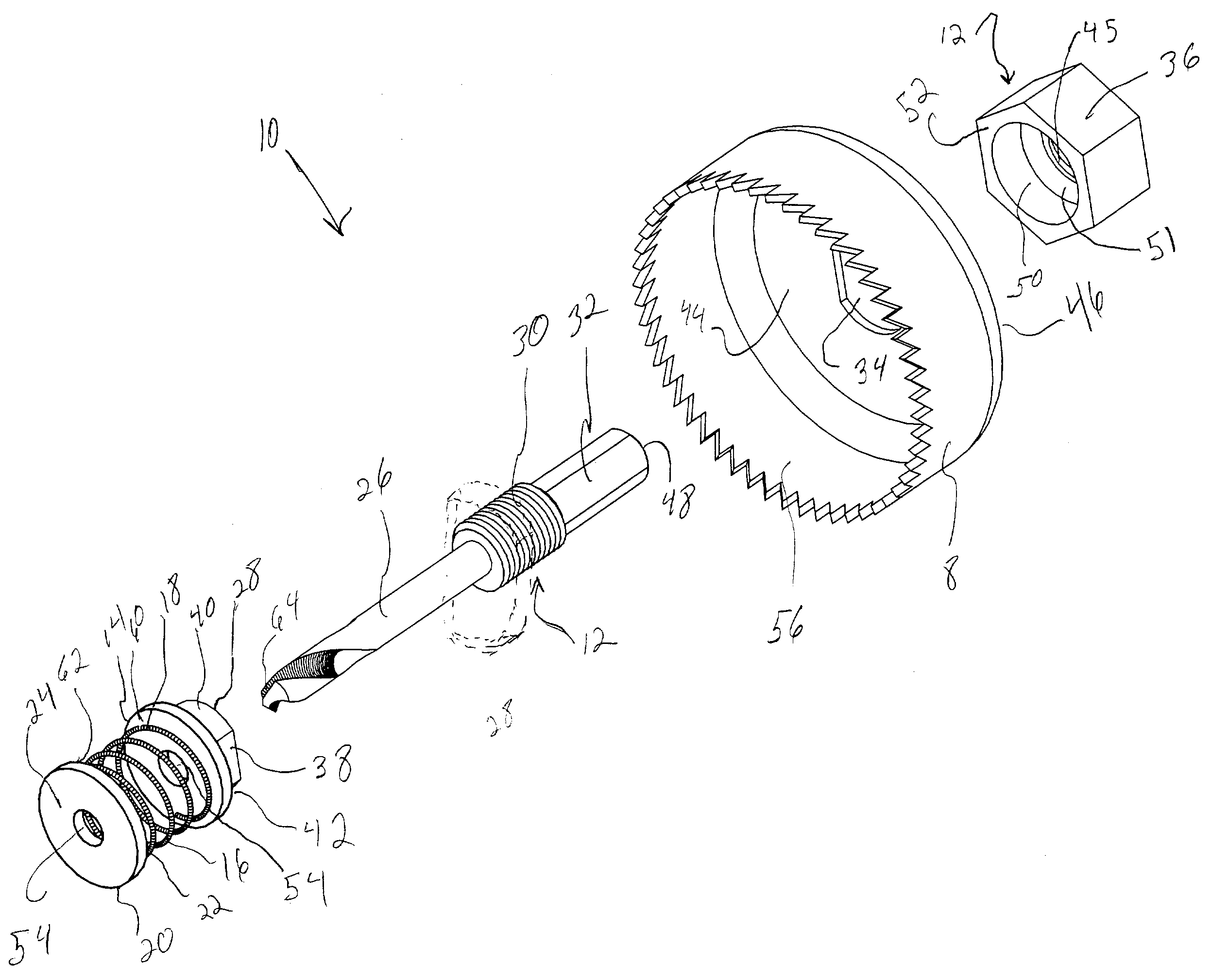
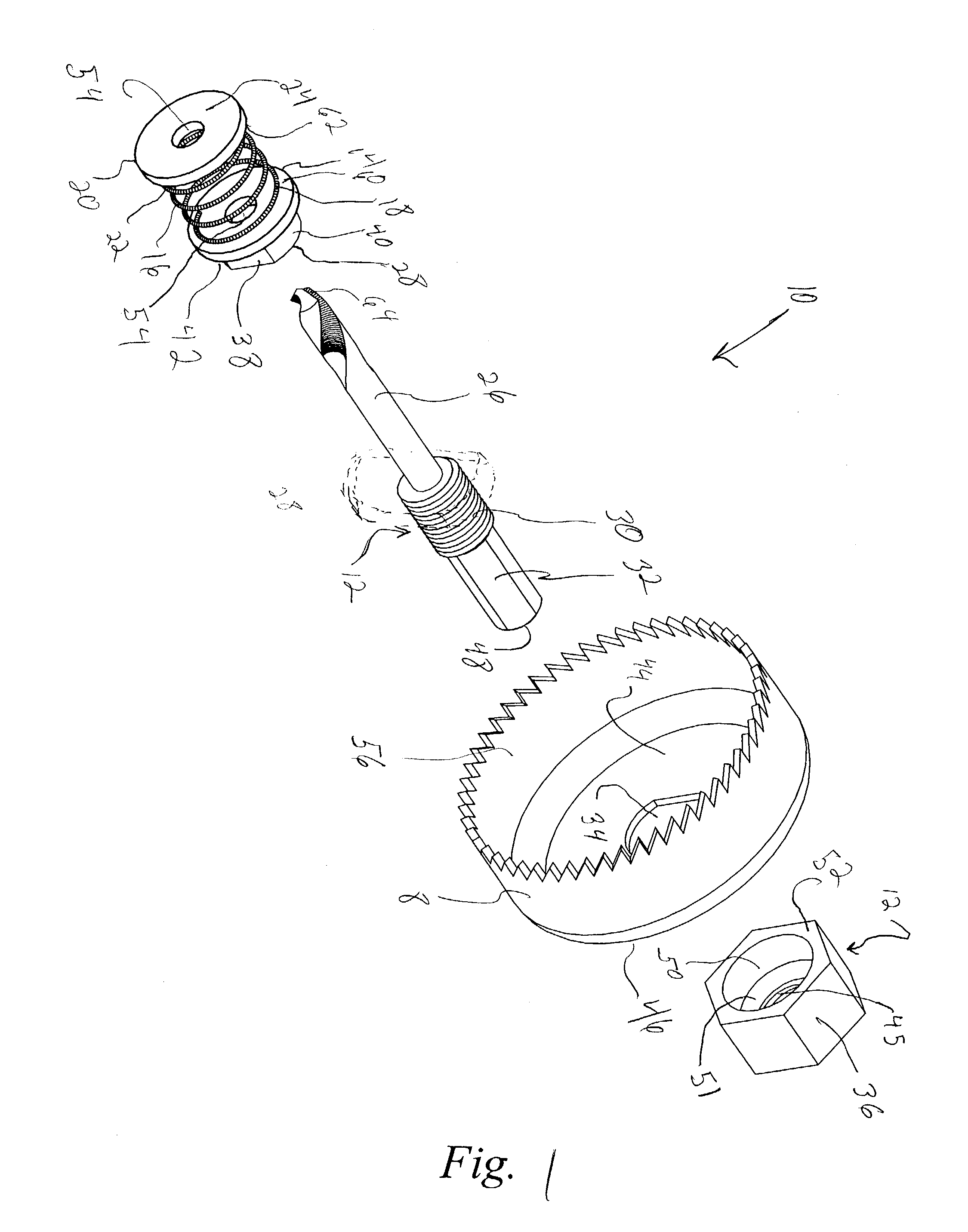
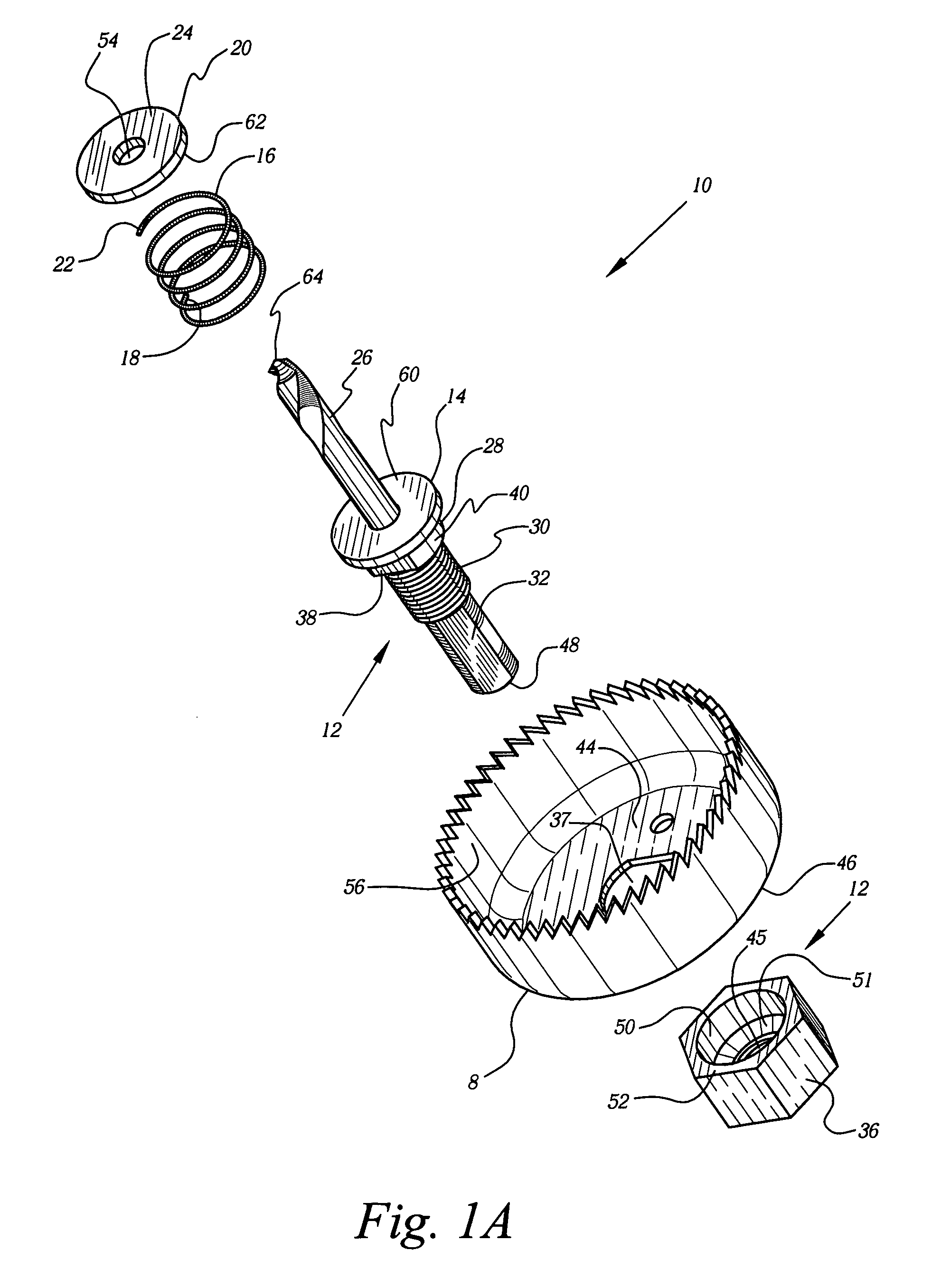
[0032]Referring now to FIGS. 1, 2 and 3, a workpiece removal device for a hole saw 8 (not part of the invention) is denoted by numeral 10. The device 10 is fabricated from metal with carbon steel being the material of choice. The device 10 includes a positioning member 12 that is detachably joined to the hole saw 8, a first securing member 14 integrally joined (via welding or similar methods) to the positioning member 12, a biasing member or spring 16 having a first end 18 integrally joined to the first securing member 14, and a second securing member 20 integrally joined to a second end 22 of the spring 16. An outer wall 24 of the second securing member 20 is ultimately disposed to communicate (irrespective of the orientation of the hole saw 8) with a preselected portion of the workpiece to promote the severance of the preselected portion from the workpiece by the hole saw 8. As the hole saw 8 cuts deeper into the workpiece, the spring 16 is increasingly compressed until the hole s...


PUM

PropertyMeasurementUnit
Forceaaaaaaaaaa

Abstract

A workpiece removal device 10 for a hole saw 8 includes a positioning member 12 joined to the hole saw 8, a first securing member 14 joined to the positioning member 12, a biasing member 16 having a first end 18 joined to the first securing member 14; a second securing member 20 joined to a second end 22 of the biasing member 16; and disposing the second securing member 20 in communication with a workpiece whereby a preselected portion of the workpiece is ultimately severed from the workpiece by the hole saw, whereupon, the biasing member forcibly removes the severed preselected portion of the workpiece from the hole saw.

Description

BACKGROUND OF THE INVENTION[0001]1. Field of the Invention[0002]The present invention relates to hole saws and more particularly, to a workpiece removal device for a hole saw.[0003]2. Background of the Prior Art[0004]Hole saws are commonly used to cut out annular portions from a workpiece. The workpiece may include wood, drywall, plaster and cylinder blocks. The annular cut out portion may be utilized for piping, electrical conduit or access portals to wiring and control equipment. The hole saw includes a drill bit that penetrates a workpiece to stabilize the hole saw assembly, including a rotary drive tool, as a cutting portion of the hole saw engages the workpiece. The cutting portion ultimately severs a predetermined portion of the workpiece thereby providing an aperture after the cutting portion and the severed portion “stuck” in an internal cavity of the hole saw, is extracted from the workpiece.[0005]The problem with prior art hole saws is that the severed portion inside the h...

Claims


Application Information

Patent Timeline
IPC IPC(8): B23B51/04
CPCB23B51/0426B23B51/0453B23B51/0473Y10T408/51Y10T408/895Y10T408/50
Inventor KOZAK, BURTON
Owner EAZYPOWER CORP
Features
  • Generate Ideas
  • Intellectual Property
  • Life Sciences
  • Materials
  • Tech Scout
  • Unparalleled Data Quality
  • Higher Quality Content
  • 60% Fewer Hallucinations
Learn More