
Drill chuck

a drill chuck and drill bit technology, applied in mechanical equipment, transportation and packaging, other domestic objects, etc., can solve problems such as disruption effects, and achieve the effect of improving the drill chuck and reducing manufacturing and assembly costs

Active Publication Date: 2016-08-18
ROHM GMBH
View PDF2 Cites 2 Cited by
  • Summary
  • Abstract
  • Description
  • Claims
  • Application Information

AI Technical Summary

Benefits of technology

This patent text describes an improved drill chuck design that reduces manufacturing and assembly costs. The invention uses an undivided threaded ring that is axially secured by a locking sleeve, which offers the advantage of carrying the ring of locking recesses. The threaded ring can be hardened with minimal deformation, and the locking sleeve achieves radial and centering securing of the ring. The locking sleeve can have a center section carrying the ring of locking recesses, which makes the drill chuck more compact. Alternatively, a retaining ring can be used to support the threaded ring in a rotationally fixed and axially immovable manner, which prevents stress on the locking device when drilling through a workpiece. The adjusting sleeve can also have a radial sleeve shoulder for improved radial guidance.

Problems solved by technology

While the customary assembly of the drill chuck can take place from the axial direction, the assembly of the divided threaded ring requires a working direction rotated by 90°, which has a disruptive effect in an automated assembly process.

Method used


Image

  • Drill chuck
  • Drill chuck
  • Drill chuck

Examples


Embodiment Construction

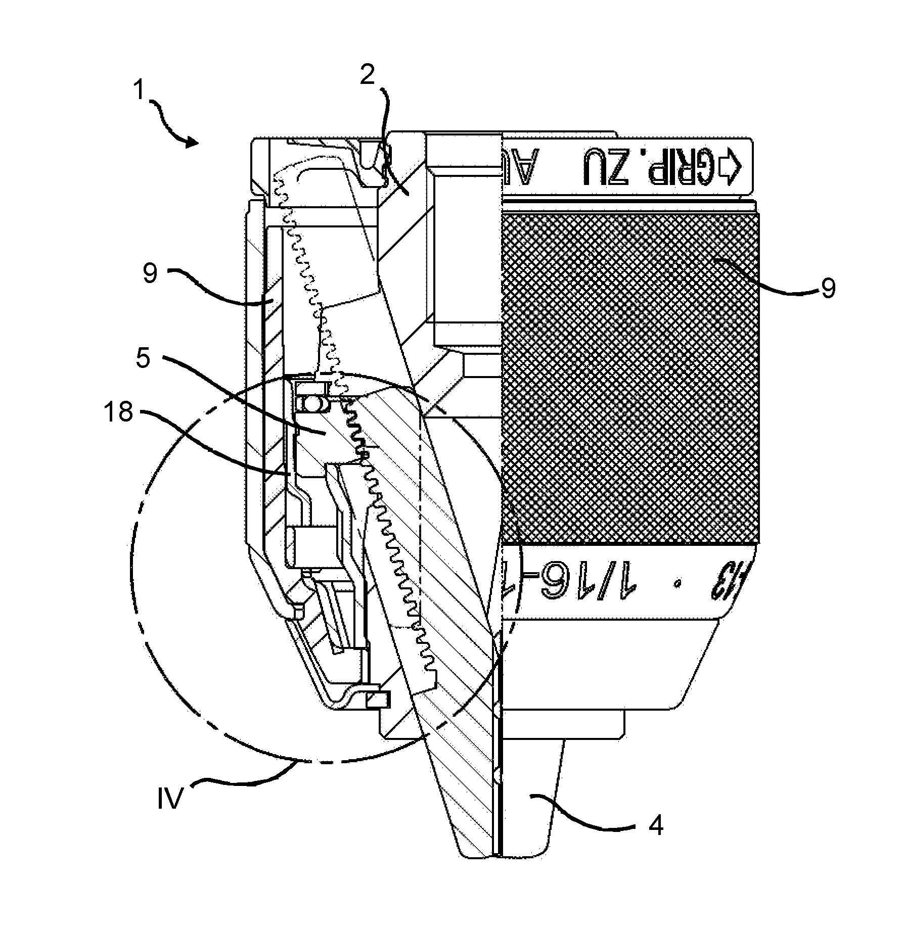
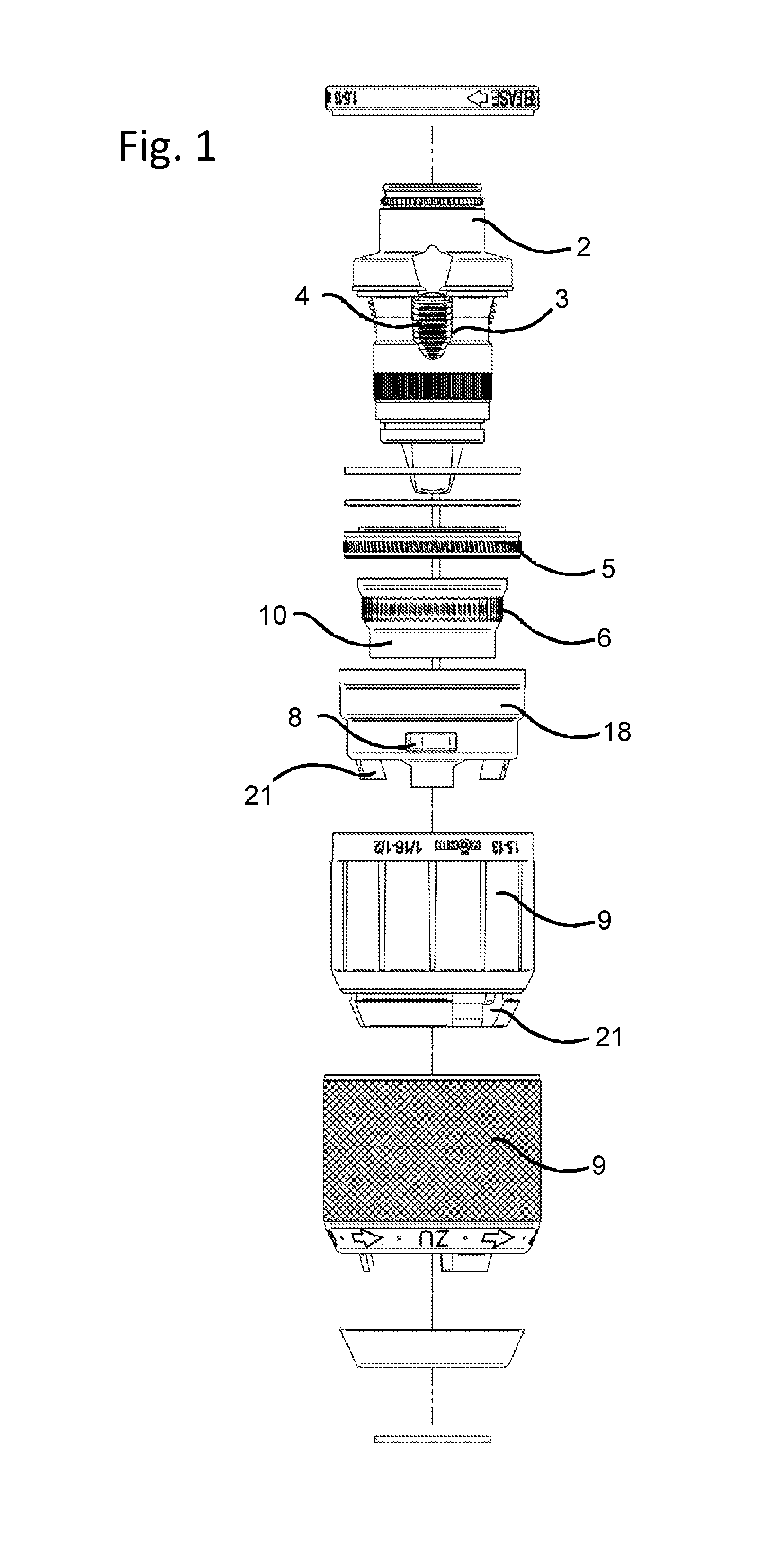
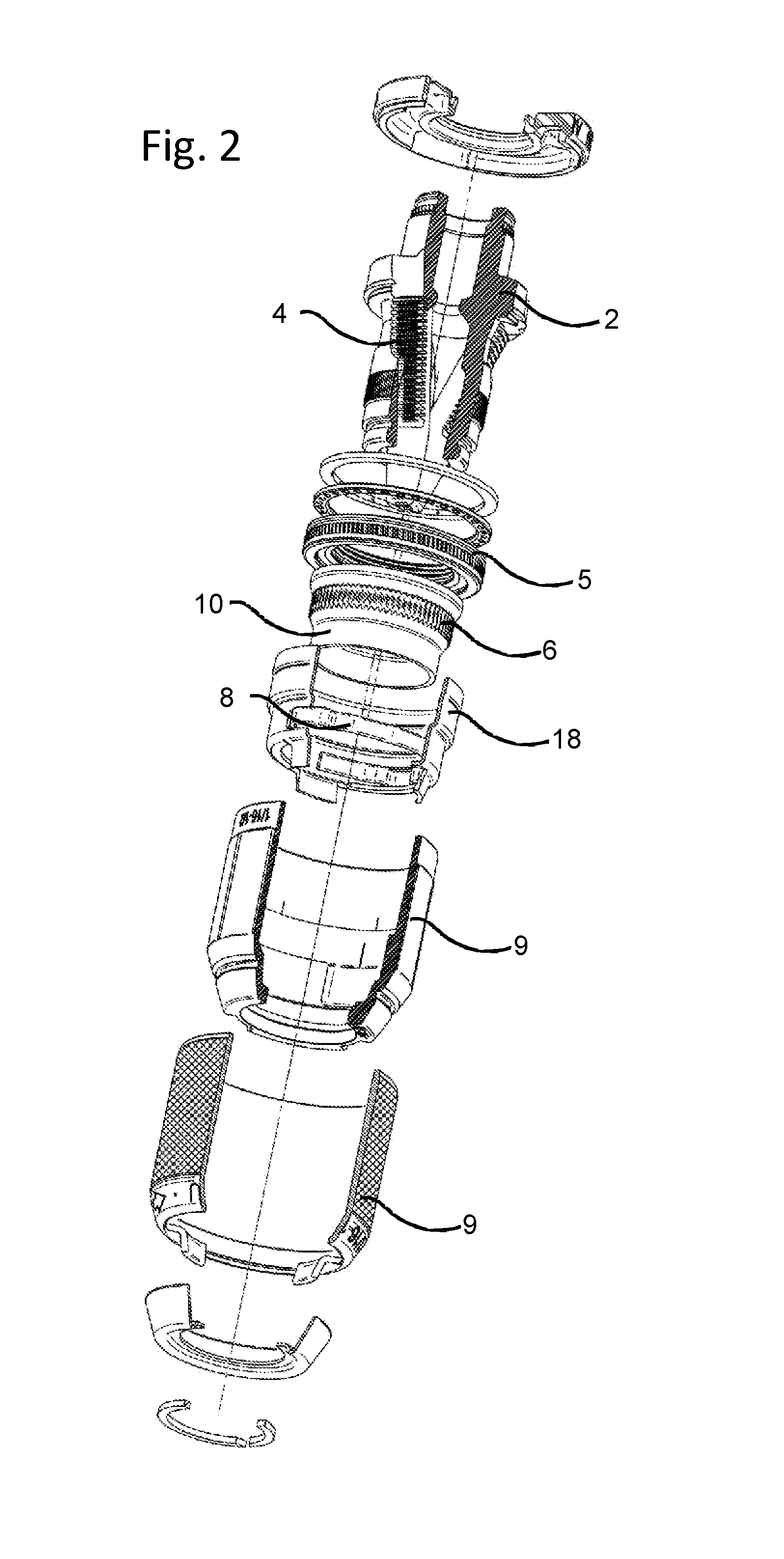
[0029]In the drawings, a first embodiment of a drill chuck 1 according to the invention is shown in an exploded view in FIGS. 1 and 2. It is evident therefrom that the drill chuck 1 has a chuck body 2 that can be connected to a drilling spindle, in which body are arranged clamping jaws 4 in guide seats 3 extending at an angle to the chuck axis, which jaws are movable for opening and closing by means of a threaded ring 5 that is arranged to be rotatable and axially immovable relative to the chuck body 2. The rotational position of the threaded ring 5 can be fixed in order to present unwanted displacements of the clamping jaws 4. This purpose is served by a locking device that is formed between the threaded ring 5 and the chuck body 2 and includes a coaxial ring 6 of locking recesses on the side of the chuck body 2 and at least one locking element 7 on the side of the threaded ring 5 that engages the locking recesses with the force of a locking spring 8. In this design, the locking el...


PUM

PropertyMeasurementUnit
Forceaaaaaaaaaa
Angleaaaaaaaaaa
Diameteraaaaaaaaaa

Abstract

A drill chuck having a chuck body connectable to a drilling spindle, in which are arranged clamping jaws in guide seats extending at an angle to the chuck axis, which jaws are movable for opening and closing via a threaded ring that is arranged to be rotatable and axially immovable relative to the chuck body. A locking device includes a coaxial ring of locking recesses as well as at least one locking element that is engaged in the locking recesses under the force of a locking spring. An adjusting ring rotatable to a limited extent between stops, the rotation of which adjusts the locking element. A detent device creating two detent positions in the circumferential direction. The threaded ring is designed as an undivided threaded ring with an opening width that is larger than the diameter of the axially forward section of the chuck body. Attached to the axially forward section of the chuck body in a rotationally fixed and axially immovable manner is a locking sleeve that carries the ring of locking recesses and serves to axially secure the threaded ring.

Description

[0001]This nonprovisional application claims priority under 35 U.S.C. §119(a) to German Patent Application No. 10 2015 102 241.9, which was filed in Germany on Feb. 17, 2015, and which is herein incorporated by reference.BACKGROUND OF THE INVENTION[0002]1. Field of the Invention[0003]The invention relates to a drill chuck having a chuck body that can be connected to a drilling spindle, in which body are arranged clamping jaws in guide seats extending at an angle to the chuck axis, which jaws are movable for opening and closing by means of a threaded ring that is arranged to be rotatable and axially immovable relative to the chuck body, having a locking device having a coaxial ring of locking recesses as well as at least one locking element that is engaged in the locking recesses under the force of a locking spring, having an adjusting ring that can be rotated to a limited extent between stops, the rotation of which adjusts the locking element, and having a detent device creating two...

Claims


Application Information

Patent Timeline
IPC IPC(8): B23B31/12B21D22/26B21H7/14
CPCB23B31/123B21D22/26B21H7/14B23B31/1238B23B31/02B21D51/16B21K1/30Y10T279/17623Y10T279/17632
Inventor SCHENK, PETERHENGSBERGER, PATRICK
Owner ROHM GMBH
Features
  • Generate Ideas
  • Intellectual Property
  • Life Sciences
  • Materials
  • Tech Scout
  • Unparalleled Data Quality
  • Higher Quality Content
  • 60% Fewer Hallucinations
Learn More