Mold cased circuit breaker

a circuit breaker and mold case technology, applied in the direction of protective switch details, protective switch operating/release mechanisms, contacts, etc., can solve problems such as safety failure problems

Active Publication Date: 2007-09-20
LS IND SYETEMS CO LTD
View PDF10 Cites 23 Cited by
  • Summary
  • Abstract
  • Description
  • Claims
  • Application Information

AI Technical Summary

Benefits of technology

[0026]The upper link is lopsidedly formed with a stopper toward the latch pin for preventing the upper link and the lower link from being positioned on a straight line and for supporting the upper link.

Problems solved by technology

In a nutshell, if the stationary contactors (112) and movable contactors (124) are not separated due to a fused-like engaged state and if the handle (114) indicates a tripped position or a reset position, the stationary contactors (112) and movable contactors (124) should be forcibly separated, but the conventional mold cased circuit breaker thus described suffers from a drawback that an actual circuit state and a handle-indicating state are different to thereby cause a safety failure problem.

Method used


Image

  • Mold cased circuit breaker
  • Mold cased circuit breaker
  • Mold cased circuit breaker

Examples


Embodiment Construction

[0038]Reference will now be made in detail to exemplary embodiments of the present disclosure, embodiments of which are illustrated in the accompanying drawings.

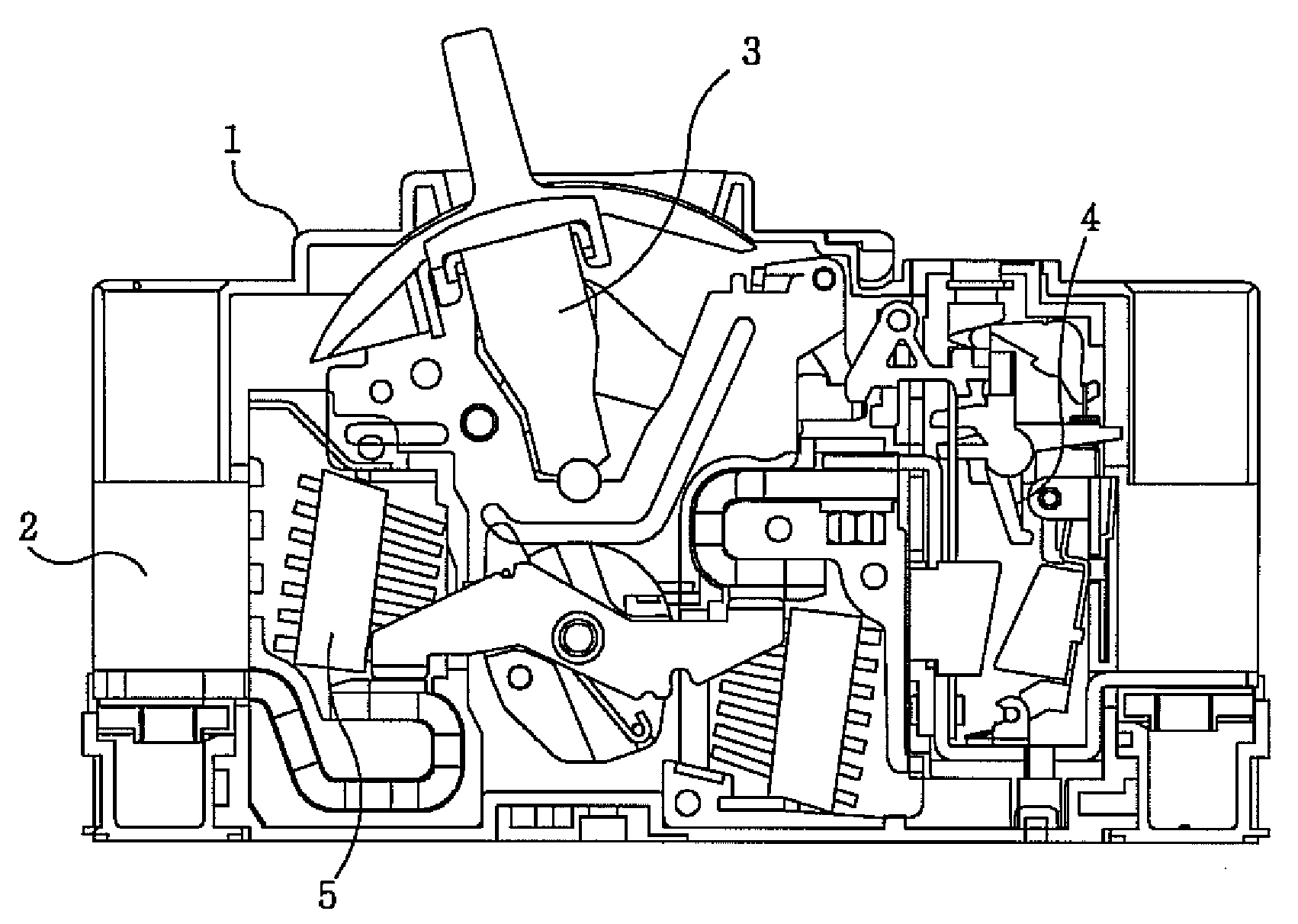
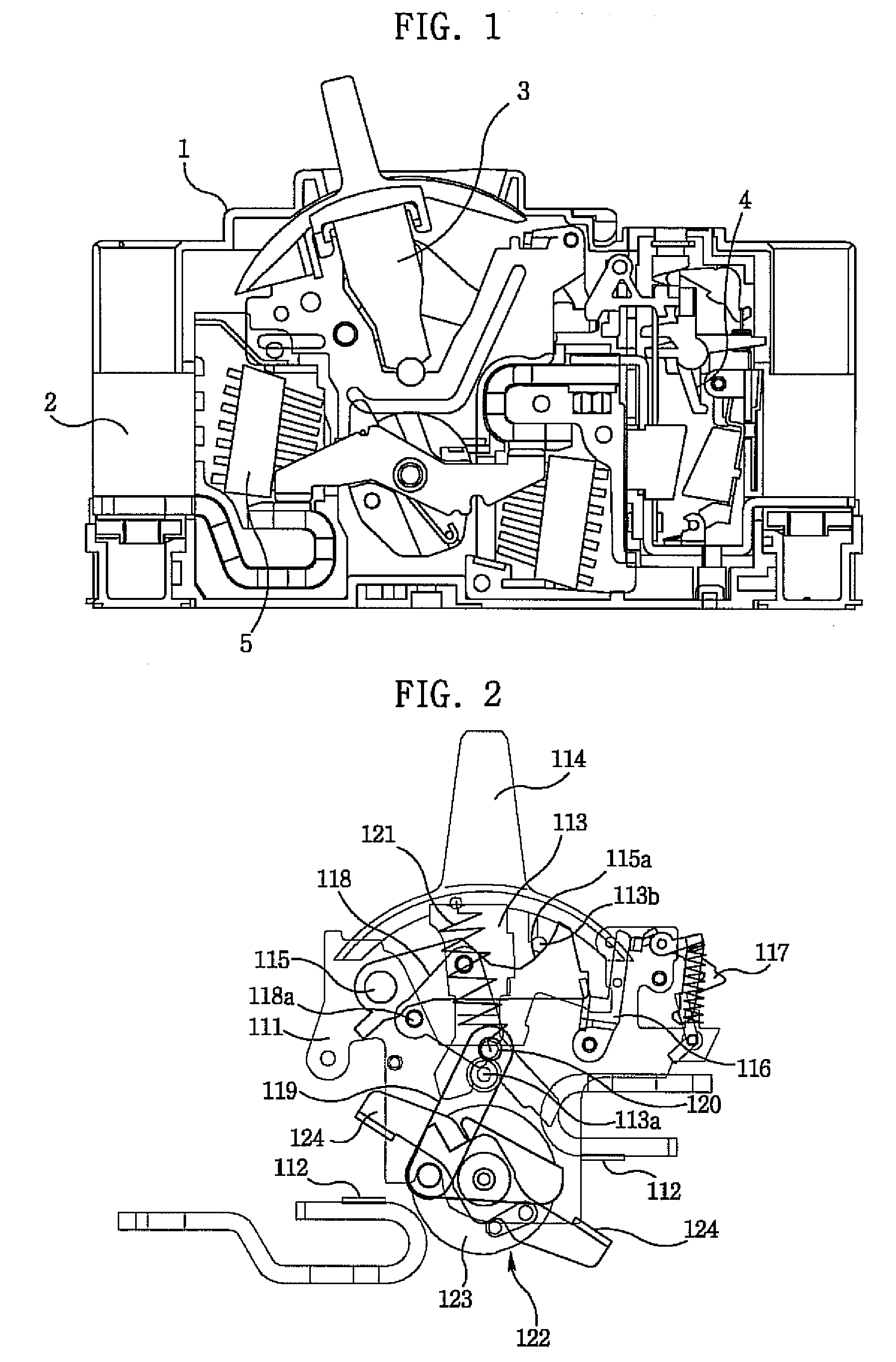
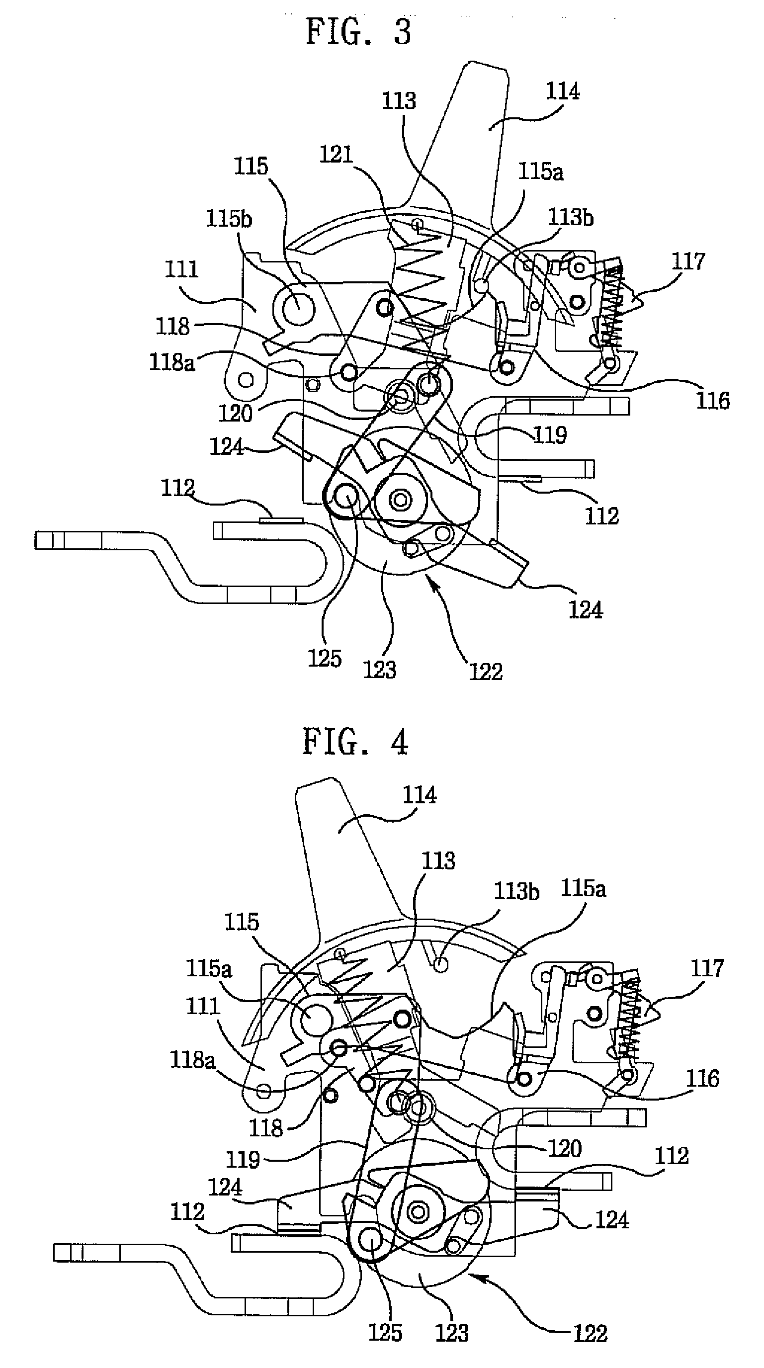
[0039]Referring to FIG. 7, a mold cased circuit breaker is configured with a contactor separation means for forcibly separating movable contactors and stationary contactors when these two contactors are tightly engaged, where the mold cased circuit breaker is comprised of a base mounted with a pair of stationary contactors and side plates, a lever connected thereon with a handle and rotatably mounted at the side plates, a latch rotatably mounted at the side plates so as to be selectively restrained by a latch holder, a nail selectively restraining the latch holder, an upper link hinged to the latch, a shaft unit including movable contactors contacting the stationary contactors disposed at the base and rotated by the side plates, a lower link hinged thereon to the upper link using a toggle pin and hinged thereunder to the sha...


PUM


Abstract

A mold cased circuit breaker is disclosed that enables a user to easily discern an actually connected state between stationary contactors and movable contactors and forcibly separates a connection therebetween if there arises electrical fault, wherein the circuit breaker comprises: a first isolation link hinged at a lower end thereof to a shaft unit and selectively engaged at an upper end thereof with a lateral surface of a lever; a second isolation link centrally formed with an oblong hole for accommodating a guide pin protruded on a side plate and linked at one end thereof to an upper end of the first isolation link; and an isolation lever adjacently positioned at one end thereof to the other end of the second isolation link, and so positioned at the other end thereof as to selectively engage with a nail, and rotatably mounted at the side plate to rotate the nail by way of operation of the second isolation link.

Description

CROSS-REFERENCE TO RELATED APPLICATION[0001]The present application is based on, and claims priority from, Korean Application Number 20-2006-0007250, filed Mar. 17, 2006, the disclosure of which is incorporated by reference herein in its entirety.BACKGROUND ART[0002]Aspects of the following description are directed to a mold cased circuit breaker (so called abbreviated MCCE) for protecting a circuit against an electrical overload by forcibly interrupting the circuit, and more particularly to a mold cased circuit breaker capable of forcibly separating a contact during a circuit fault by allowing a user to easily notice a state of the contact.[0003]Typically, circuits are disposed at one side thereof with a mold cased circuit breaker for protecting the circuit against an electrical overload.[0004]Referring to FIG. 1, a conventional mold cased circuit breaker incorporates a cover (1), a base (2), a switching mechanism (3) for opening and closing a circuit, a tripping device (4) for det...

Claims


Application Information

Patent Timeline
Patent Type & Authority Applications(United States)
IPC IPC(8): H01H9/30
CPCH01H1/2041H01H71/525H01H71/501H01H71/52H01H73/24
Inventor PARK, JIN YOUNG
Owner LS IND SYETEMS CO LTD
Why Eureka
Try Eureka