Reversibly deployable air dam

a technology of air dam and reversible deployment, which is applied in the direction of roofs, transportation and packaging, vehicle arrangements, etc., can solve the problems of airflow relative to the vehicle not being able to be adjusted to better suit the changing driving conditions, the device generally does not adapt, and the downforce can affect the stability and handling of the vehicl

Active Publication Date: 2007-09-20
GM GLOBAL TECH OPERATIONS LLC
View PDF7 Cites 57 Cited by
  • Summary
  • Abstract
  • Description
  • Claims
  • Application Information

AI Technical Summary

Benefits of technology

[0009] Disclosed herein are air dams that define a surface of the vehicle that can, through its alterable ground clearance, modify the airflow under the vehicle during movement of the vehicle. In one embodiment, a vehicle air dam system comprises a housing having a opening; an airflow control member translatably disposed within the housing and slidably engaged with the opening; and an active material actuator comprising an active material in operative communication with the airflow control member to effect deployment and retraction of the airflow control member from and into the housing.

Problems solved by technology

Vehicle lift and downforce can affect vehicle stability and handling.
Such devices generally do not adapt as driving conditions change, thus the airflow relative to the vehicle cannot be adjusted to better suit the changing driving conditions.
Vehicle designers are faced with the challenge of controlling the airflow while maintaining sufficient ground clearance to avoid contact with and damage by parking ramps, parking blocks, potholes, curbs and the like.
Further, inclement weather, such as deep snow, slush or rainfall, can damage the device and / or impair vehicle handing.
However, such actuators generally require additional components such as pistons, motors, solenoids and / or like mechanisms for activation, which increase the complexity of the device often resulting in increased failure modes, maintenance, and manufacturing costs.
The use of spoilers increases the cornering capability and improves stability at high speeds, but often at the expense of additional aerodynamic drag and weight.
Such devices can thus not be relocated, reoriented, reshaped, etc. as driving conditions change and thus airflow over / under / around the vehicle body can not be adjusted to better suit the changed driving condition.
Also, current air dams reduce the vehicle's ground clearance, and thus presents a constant challenge to designers to provide the needed control of airflow while maintaining sufficient ground clearance to avoid contact with and being damaged by parking ramps, parking blocks, and encounters with potholes and curbs.
Along these lines underbody airflow control devices, if they extend sufficiently close to the ground, can present a problem with regards to driving through deep standing water, slush, snow, and off-road unpaved surfaces.

Method used


Image

  • Reversibly deployable air dam
  • Reversibly deployable air dam
  • Reversibly deployable air dam

Examples


Embodiment Construction

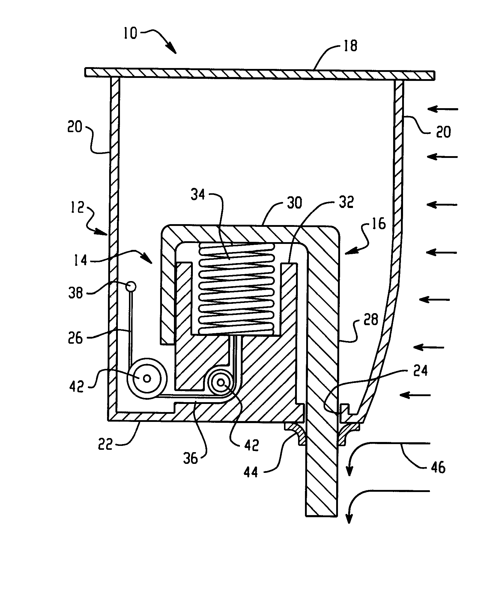
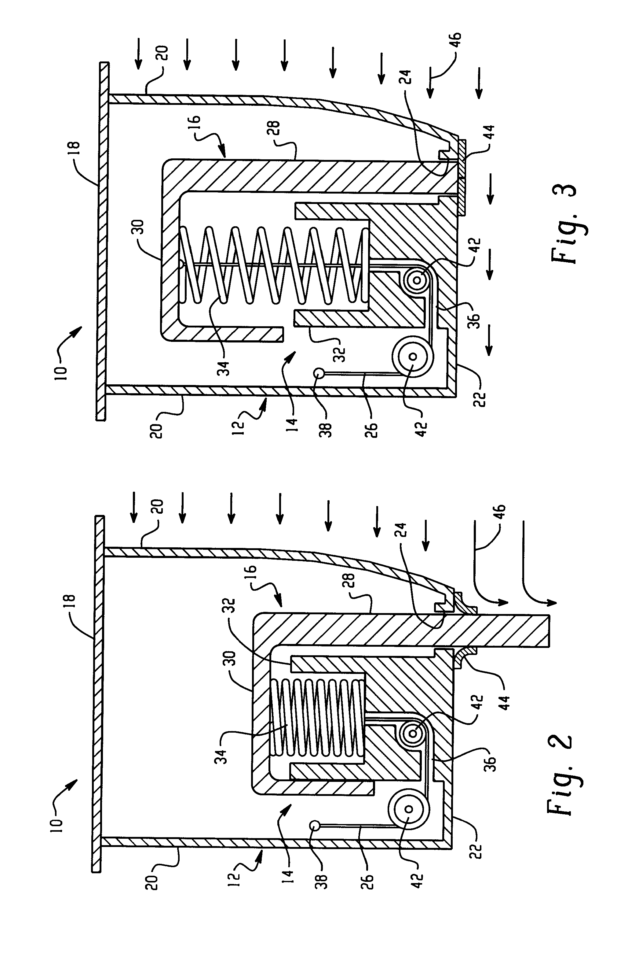
[0023] Active material actuated reversibly deployable air dams are disclosed herein. The air dams are suitable for use on a vehicle on which it might be desirable to have tunable frontal airflow restrictors that are designed to smooth the flow of air around and under a vehicle as may be desired by the driving conditions, selectively decrease the coefficient of drag, as well as improve fuel economy, handling, and maneuvering at high speeds such as vehicles that can be utilized on occasion in competitive driving. Even more specifically, either deployment or stowing of the air dams in these embodiments is preferably in each case based on either a rigid body translation or rotation effected through just a single activation cycle (or at most a very small number of activation cycles) of an active material. Obviously, as described above, there is benefit associated with being able to deploy / stow the air dam to match the needs of different driving conditions. Beyond this, however, there are...


PUM


Abstract

Vehicle air dams that include an airflow control member and an active material based actuator for deploying the airflow control member so as to change airflow about the vehicle.

Description

CROSS REFERENCE TO RELATED APPLICATIONS [0001] This application relates to and claims the benefit of priority to U.S. Provisional Patent Application No. 60 / 725,685 filed on Oct. 12, 2005, incorporated herein by reference in its entirety.BACKGROUND [0002] The present disclosure relates to airflow control devices for vehicles, and more particularly, to reversibly deployable air dams for vehicles that use active materials to effect deployment and retraction. [0003] Airflow over, under, around, and / or through a vehicle can affect many aspects of vehicle performance including vehicle drag, vehicle lift and down force, and cooling / heat exchange for a vehicle power train and air conditioning systems. Reductions in vehicle drag improve fuel economy. Vehicle lift and downforce can affect vehicle stability and handling. As used herein, the term “airflow” refers to the motion of air around and through parts of a vehicle relative to either the exterior surface of the vehicle or surfaces of elem...

Claims


Application Information

Patent Timeline
Patent Type & Authority Applications(United States)
IPC IPC(8): B62D35/00
CPCB62D35/005B62D35/007Y02T10/82B62D37/02
Inventor ROBER, KEVIN B.BROWNE, ALAN L.JOHNSON, NANCY L.AASE, JAN H.
Owner GM GLOBAL TECH OPERATIONS LLC
Why Eureka
Try Eureka