Digital impression for remote manufacturing of dental impressions

a technology of remote manufacturing and dental impressions, applied in the field of computer-aided manufacturing of dental items, can solve the problems of time-consuming activity, many patients suffering from gag reflex or breathing problems, and time-consuming impression taking process

Inactive Publication Date: 2007-09-20
D4D TECH LP
View PDF6 Cites 81 Cited by
  • Summary
  • Abstract
  • Description
  • Claims
  • Application Information

AI Technical Summary

Benefits of technology

[0007] An object of the invention is to provide a “digital impression,” in lieu of a physical impression. A suitable 3D digitizer is used to capture the digital impression, e.g., by scanning in a patient's oral cavity a preparation area, as well as adjacent and opposing dentition. A bite strip may also be scanned instead of scanning the opposing dentition. This process eliminates the taking of a physical impression. The digital impression may then be transferred immediately to a dental laboratory, e.g., via the Internet. The digital impression may include additional information of interest to the laboratory including a margin curve (which is an exterior interface between the desired restoration and the prepared area). It may also include a 3D solid model of the restoration.

Problems solved by technology

The taking of impressions is a time consuming process, and is also a process which is not enjoyed by patients.
Indeed, many patients suffer from gag reflexes or breathing problems during the several minutes that the impression materials need to be in place.
In addition, as noted above, this physical impression must be mailed or otherwise delivered to a dental laboratory, which takes at least a day but usually longer; it also needs to be turned into a model at the laboratory, which also is a time consuming activity.

Method used


Image

  • Digital impression for remote manufacturing of dental impressions
  • Digital impression for remote manufacturing of dental impressions
  • Digital impression for remote manufacturing of dental impressions

Examples


Embodiment Construction

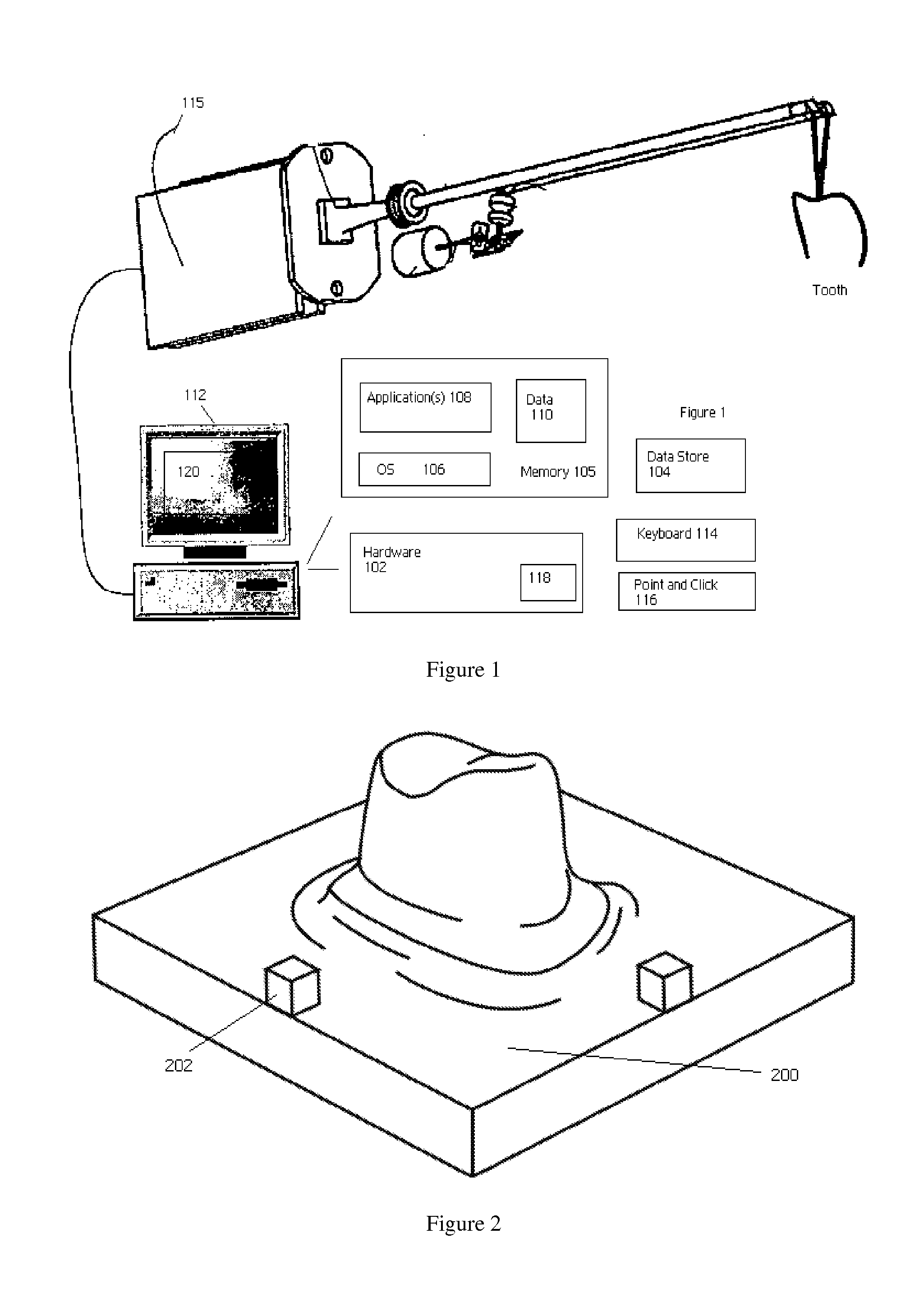
[0021] In one aspect, the present invention provides a method, preferably implemented in a computer, for generating a digital dental impression. A representative computer 100 comprises hardware 102, suitable storage 104 and memory 105 for storing an operating system 106, one or more software applications 108 and data 110, conventional input and output devices (a display 112, a keyboard 114, a point-and-click device 116, and the like), other devices 118 to provide network connectivity, and the like. A laser digitizer system 115 is used to obtain optical scans from a patient's dental anatomy. Using a conventional graphical user interface 120, an operator can view and manipulate models as they are rendered on the display 112.

[0022] A digital impression may be obtained using an intra-oral digitizer, such as the E4D Dentist system available from D4D Technologies, LLC and described by commonly-owned, co-pending U.S. Pat. No. 7,184,150. The prepared area and adjacent teeth are scanned usi...


PUM


Abstract

A “digital impression” is provided in lieu of a physical “dental” impression. A 3D digitizer is used to capture the digital impression, e.g., by scanning in a patient's oral cavity. A digital impression “data set” is formed using a computer-implemented method. The method begins by generating a three dimensional (3D) restoration model. Then, a bounding volume of the restoration model is computed. The bounding volume is defined as at least a minimum 3D volume that contains the 3D model. Thereafter, a lower solid 3D model, and an upper solid 3D model are created; these lower and upper models have a predetermined relationship with one another. In particular, when superimposed upon one another within the bounding volume, the lower and upper 3D models define a cavity into which the restoration model is adapted to fit. The restoration model, the lower solid 3D model and the upper solid 3D model are then aggregated into the data set to form the digital impression. Typically, the digital impression is generated at a first location, i.e., a dental office, and then transmitted to a second location, a dental laboratory, remote from the first location. Such transmission is conveniently done over a network, such as a TCP / IP network (e.g., the Internet). A dental item is then manufactured at the second location. Thus, for example, the lower solid 3D model may be used to build a coping, or the restoration model itself used to build a restoration. In the latter case, information in the data set may be used to check a fit of the restoration.

Description

[0001] This application is based on and claims priority from Ser. No. 60 / 779,582, filed Mar 6, 2006.BACKGROUND OF THE INVENTION [0002] 1. Technical Field [0003] The present invention relates generally to computer-aided manufacturing of dental items. [0004] 2. Background of the Related Art [0005] Traditionally, a dental restoration is produced in a four step process. The first step is performed by the dentist where the area to receive the restoration is prepared using various dental tools. The second step involves taking an impression of the prepared area as well as the opposing dentition in the bite position, and sending the preparation impression to a dental laboratory, along with specifications of the kind of restoration desired. The third step occurs at the dental laboratory where two models are poured and combined into an articulator, and now accurately represent the patient's dentition in the relevant area. The articulated model shows the prepared area and adjacent teeth, as we...

Claims


Application Information

Patent Timeline
Patent Type & Authority Applications(United States)
IPC IPC(8): A61C5/10A61C5/77
CPCA61C13/0004A61C9/0053A61C5/77G16H20/40
Inventor QUADLING, HENLEYQUADLING, MARK
Owner D4D TECH LP
Why Eureka
Try Eureka