Concrete masonry units window and door flashing and installation

a technology of concrete masonry units and flashing, applied in the direction of windows/door frames, snow traps, doors/windows, etc., can solve the problems of water damage or a potential to water damage, associated mold damage, etc., and achieve the effect of preventing damag

Inactive Publication Date: 2007-09-27
TEODOROVICH MISHKO
View PDF37 Cites 11 Cited by
  • Summary
  • Abstract
  • Description
  • Claims
  • Application Information

AI Technical Summary

Benefits of technology

[0006]The current invention is a method and system for flashing to prevent damage by draining water to the exterior of the building. This drainage is accompl

Problems solved by technology

This moisture will also enter the rough opening 106, and if not properly managed,

Method used


Image

  • Concrete masonry units window and door flashing and installation
  • Concrete masonry units window and door flashing and installation
  • Concrete masonry units window and door flashing and installation

Examples


Embodiment Construction

Window and Door Applications

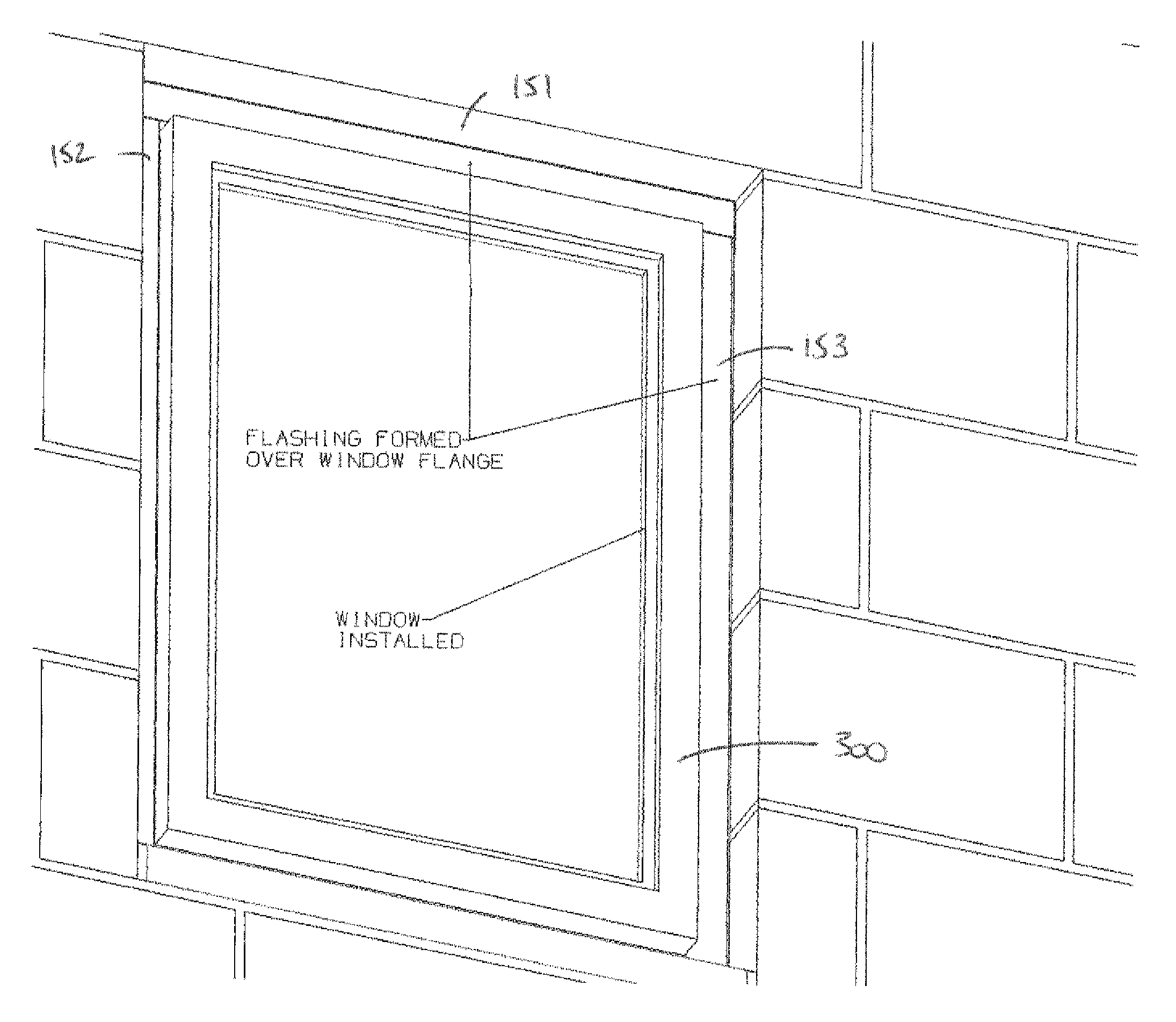
[0039]This specification incorporates by reference the specification of co-pending U.S. patent application Ser. No. 11 / 621,618 (Provisional application No. 60 / 757,684 for “Apparatus and method for door and window side flashing” filed by applicant on Jan. 10, 2007. The '618 Application describes an extruded profile SideFlash™ from Suresill. Ltd. (www.suresill.com). Referring to FIGS. 10 and 11, the SideFlash 400 has a bent portion 404 for the interior of an opening, a rigid portion 401, a flexible portion 402, and fold grooves 403 for bending the flashing around a window or door flange.

[0040]FIG. 12 is a flow chart describing a method for sealing a CMU opening with a side flashing.

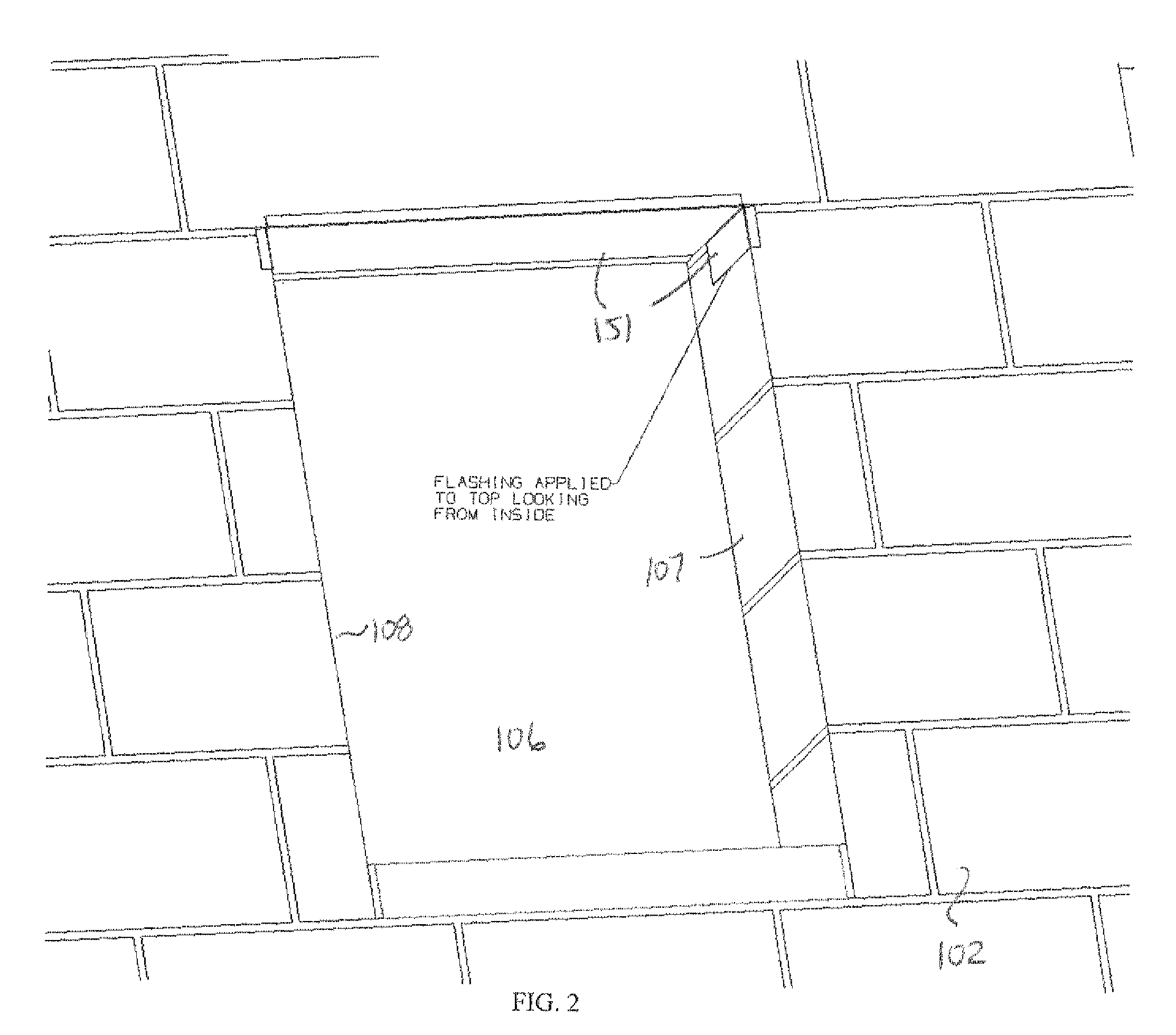
[0041]At step 1000, a side flash 151 is applied to the top portion of the rough opening. FIG. 2 is an interior perspective view of SideFlash™ flashing applied to the top 109 of rough opening 106. The bent portions of the SideFlash overlaps the interior edge of the upper portion o...


PUM


Abstract

Concrete masonry units, CMU, windows and doors are flashed by applying a side flashing to the top and sides of the rough opening before blocking, applying a sill pan in the bottom of the rough opening, and then installing the window or door. Portions of the side flashings on the top and sides of the rough opening are then bent over the side and top window or door flanges so that a portion of the side flashings may be adhered or otherwise fastened to the flanges to provide a seal.

Description

RELATED APPLICATIONS[0001]This application is related to provisional application No. 60 / 785,256 filed Mar. 23, 2006 by applicant and claims the priority date of that application.[0002]This specification incorporates by reference the specification of co-pending U.S. patent application Ser. No. 11 / 621,618 (Provisional application No. 60 / 757,684) for “Apparatus and method for door and window side flashing” filed by applicant on Jan. 10, 2007.FIELD OF INVENTION[0003]This invention relates to a door or window side flashing system, devices, and methods to direct moisture away from the inside of a CMU or Concrete Masonry Unit structure.BACKGROUND[0004]CMU or Concrete Masonry Unit, also called a concrete block, is a concrete (masonry) component for construction of certain type of walls. Buildings with exterior walls built with CMU are usually referred to as concrete block buildings or CMU buildings. Windows and doors are typically installed in CMU buildings with the assumption that the CMU ...

Claims


Application Information

Patent Timeline
IPC IPC(8): E04D1/36E04D13/14
CPCE06B2001/628E06B1/62
Inventor TEODOROVICH, MISHKO
Owner TEODOROVICH MISHKO
Why Eureka
Try Eureka