Liquid removal system and method

a liquid removal system and liquid technology, applied in the field of liquid removal system and method, can solve the problems of secondary recovery equipment no longer economically practicable and well abandoned

Inactive Publication Date: 2007-09-27
UNDERWOOD JERRY
View PDF17 Cites 1 Cited by
  • Summary
  • Abstract
  • Description
  • Claims
  • Application Information

AI Technical Summary

Benefits of technology

[0004] The present invention provides a method and system capable of economically removing a liquid from a ...

Problems solved by technology

However, because of the costs of typical lift equipment, secondary recovery methods are pursued only if the oil field is believed to make the addition...

Method used


Image

  • Liquid removal system and method
  • Liquid removal system and method
  • Liquid removal system and method

Examples


Embodiment Construction

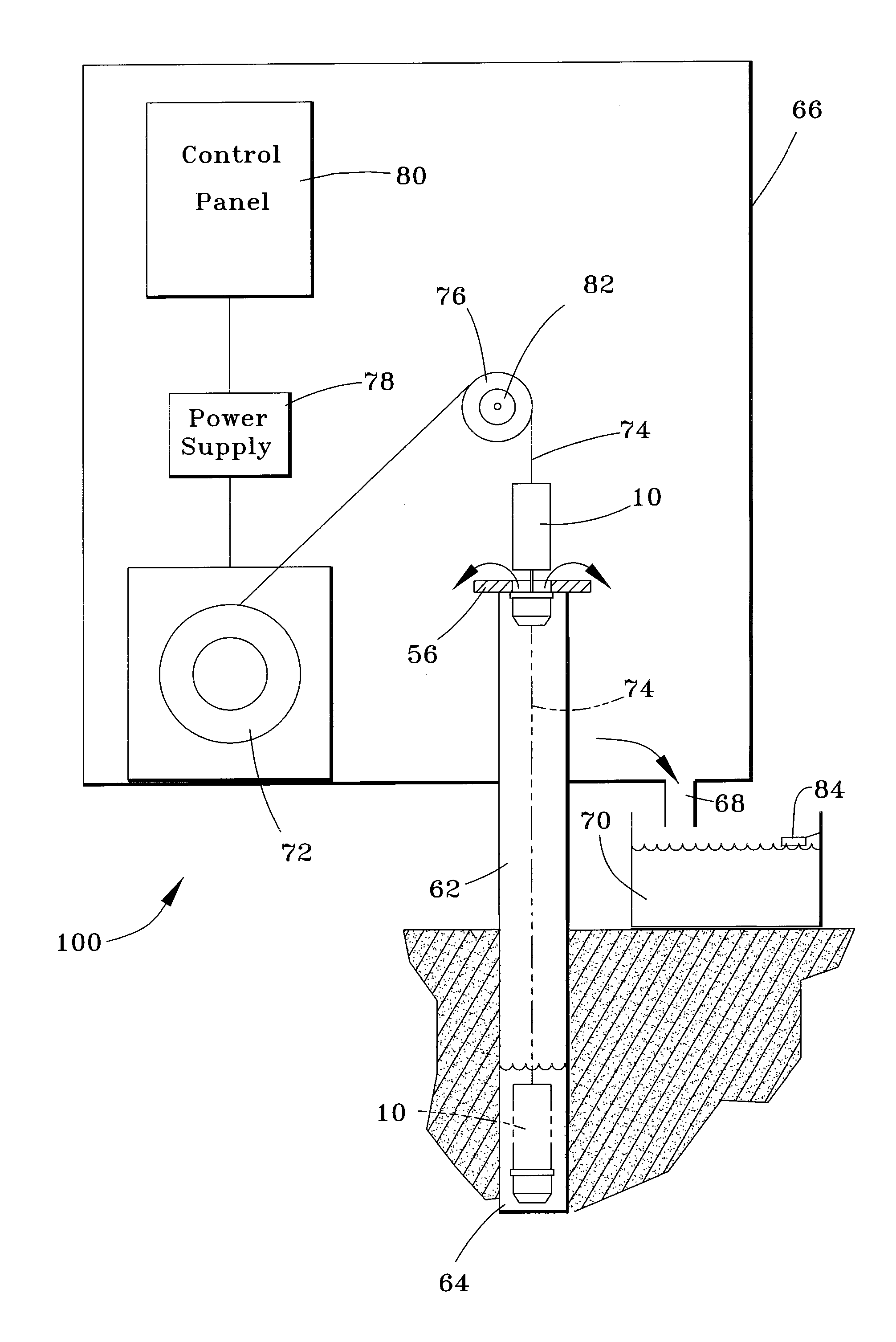
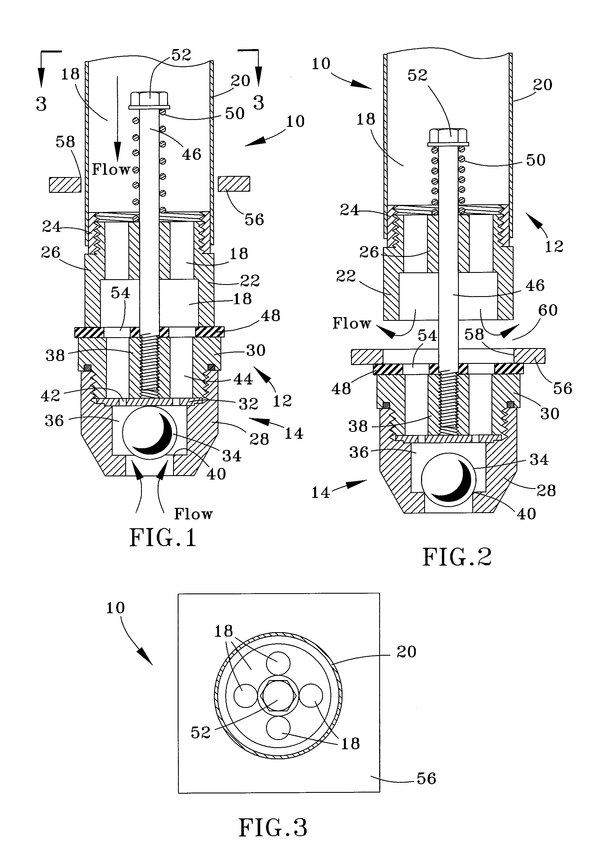
[0013]FIGS. 1 through 3 depict a dipping unit 10 for use in removing a liquid from a liquid reservoir. A particularly notable application for the unit 10 is an oil recovery system 100 shown in FIG. 4. Though the invention will be described below in reference to an oil well recover system and method, the invention is not so limited. For example, the dipping unit 10 is also well suited for removing water from a water well or other water source or reservoir, such as for the purpose of obtaining water samples for testing, etc.

[0014] From FIGS. 1 and 2, it can be seen that the dipping unit 10 generally has upper and lower end portions 12 and 14 held together with a biasing assembly 16. A fill chamber 18 is defined in the upper end portion 12 of the unit 10 by a tube 20, a dump adapter 22, and a fitting 24 that secures the dump adapter 22 to the tube 20. While the fitting 24 is represented as being attached (e.g., welded) to the tube 20 and threaded into the adapter 22, other assembly me...


PUM


Abstract

A method and system capable of economically removing a liquid from a liquid reservoir, such as oil from an oil reservoir, by withdrawing limited quantities of the liquid in discrete steps. The system includes a dipping unit sized to be received in a passage to the reservoir, such as a casing of an oil well, and a unit for lowering and raising the dipping unit within the passage. The dipping unit is configured and oriented to have an upper end portion and a lower end portion when within the passage. The dipping unit includes a chamber, a feature for enabling a liquid to enter the chamber when at least its lower end portion is submerged in the liquid within the reservoir, and a feature for releasing the liquid from the chamber. In use, the dipping unit is lowered within passage to a liquid reservoir to enable liquid to flow into the chamber of the dipping unit when at least a lower end portion of the dipping unit is submerged in the liquid within the reservoir, and then raising the dipping unit within the passage so that the liquid is released from the chamber.

Description

CROSS REFERENCE TO RELATED APPLICATIONS [0001] This application claims the benefit of U.S. Provisional Application No. 60 / 785,153 filed Mar. 23, 2006, the contents of which are incorporated herein by reference.BACKGROUND OF THE INVENTION [0002] The present invention generally relates to equipment and methods for removing liquids from liquid reservoirs, for example, oil well recovery equipment and methods capable of economically removing oil from an oil field. [0003] An oil well is typically constructed to have a tubing within one or more casings that structurally support the wellbore and seal the wellbore (other than the tubing) at the surface, typically so that the pressure of the oil within the oil field is sufficient to force oil through the tubing to the surface. As an oil field is depleted, this pressure can drop to a sufficiently low level to necessitate the use of artificial lift methods and equipment, examples of which include downhole pumps, gas lifts, and surface pump-jack...

Claims


Application Information

Patent Timeline
IPC IPC(8): E21B34/04
CPCE21B34/08E21B43/126E21B34/105
Inventor UNDERWOOD, JERRY
Owner UNDERWOOD JERRY
Why Eureka
Try Eureka