Thermostatic mixing valve

a technology of mixing valve and thermostatic valve, which is applied in the direction of thermometer, mixer, instruments, etc., can solve the problems of unsatisfactory experience, unsatisfactory approach, and general poor valve performan

Inactive Publication Date: 2007-09-27
KOHLER MIRA LTD
View PDF14 Cites 16 Cited by
  • Summary
  • Abstract
  • Description
  • Claims
  • Application Information

AI Technical Summary

Benefits of technology

[0013] It is a desired object of the present invention to provide an improved thermostatic mixing valve that is operable in a reliable manner.

Problems solved by technology

A sudden increase or decrease in temperature that is sufficient to be discernible to the user may result in an uncomfortable experience.
The size and duration of any temperature overshoot or undershoot may only last a few seconds but is again discernible to the user if more than a few degrees and can be uncomfortable even if not presenting a safety risk.
This approach has not been completely successful, however, and in many cases valve performance is generally not as good as predicted by theoretical calculations.
Such skewing of the response is undesirable however as it may not result in optimum performance for all the circumstances that may arise in use.
As a result of extensive testing, we have now found that in many existing valve designs incomplete mixing of the water occurs and the water temperature detected by the thermal control system is made up of the temperature of partially mixed and unmixed streams of hot and cold water.
This adds considerably to production costs and the fundamental problem of variations in performance between valves assembled from the same components still persists.
If the streams of hot and cold water entered the mixing chamber on opposite sides of the mixing chamber, there would be a risk that the higher energy stream could suppress the flow of the lower energy stream, resulting in a sudden deviation from the intended proportions of hot and cold water.
An instability of the whole valve could result.

Method used


Image

  • Thermostatic mixing valve
  • Thermostatic mixing valve
  • Thermostatic mixing valve

Examples


first embodiment

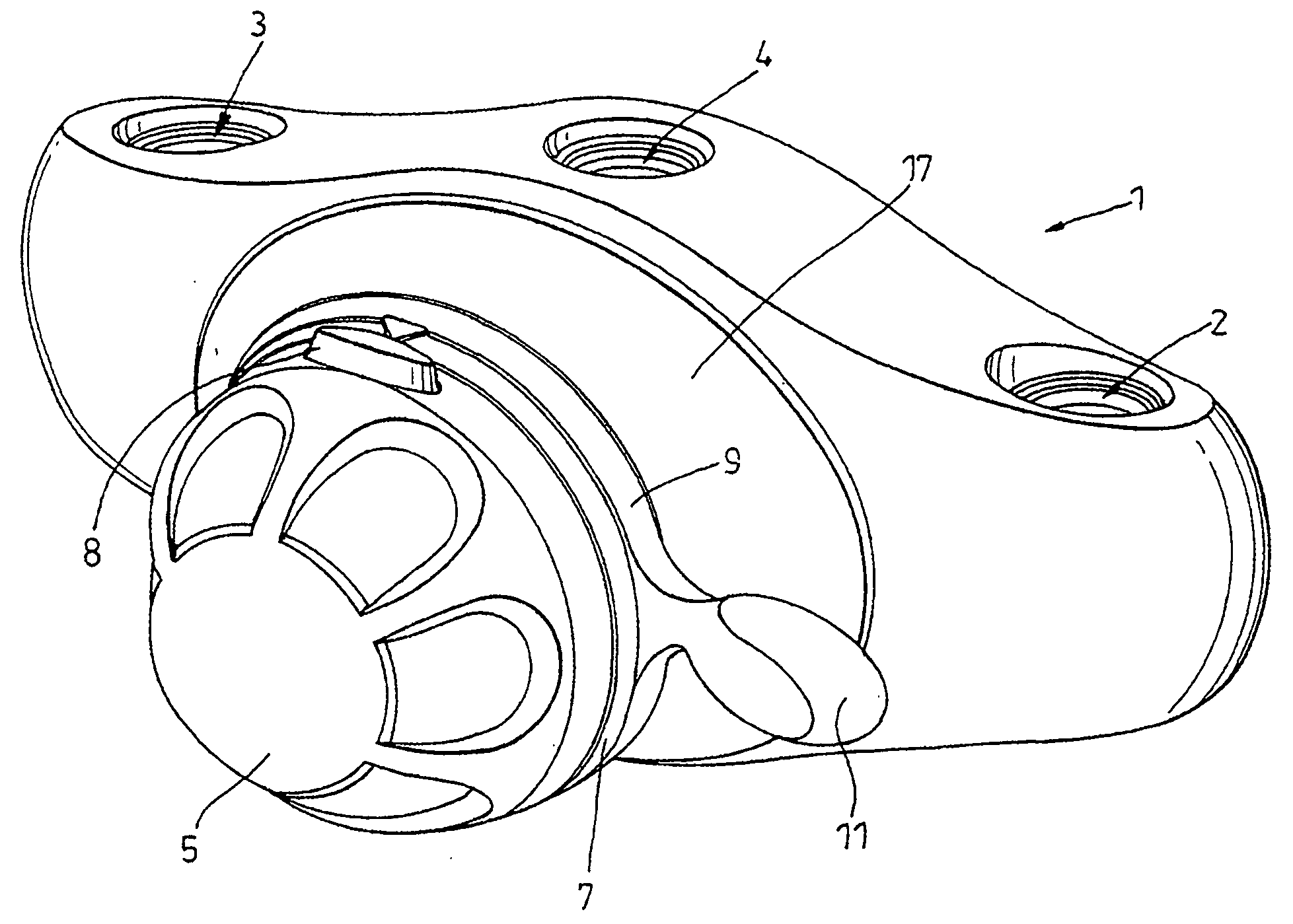
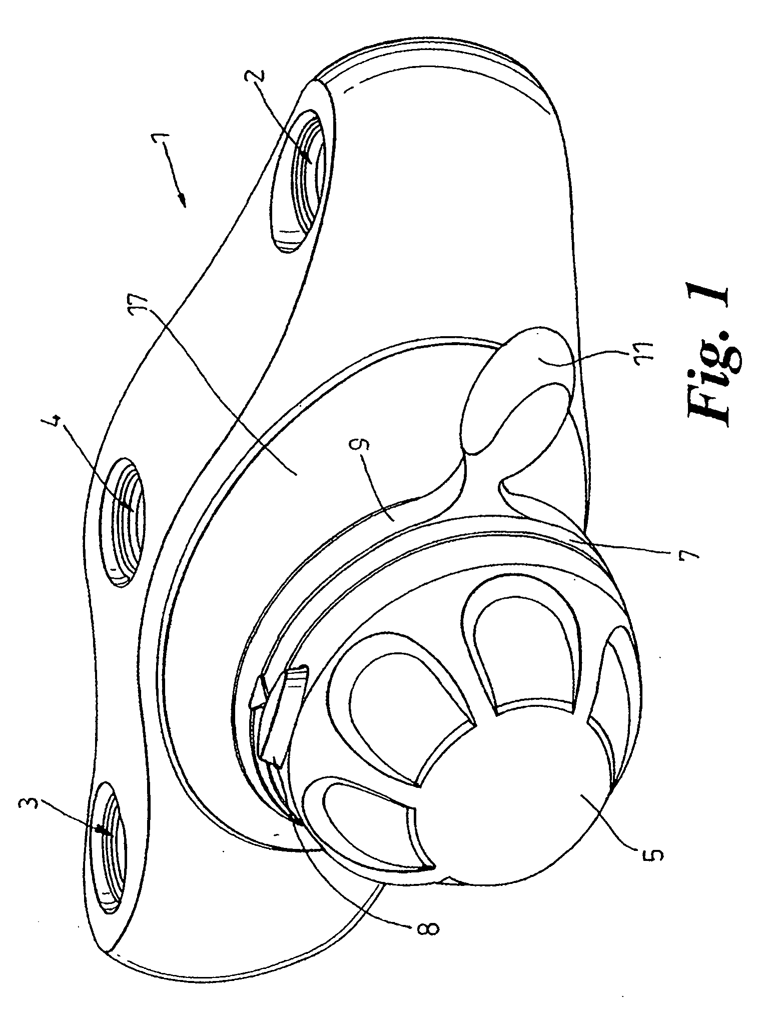
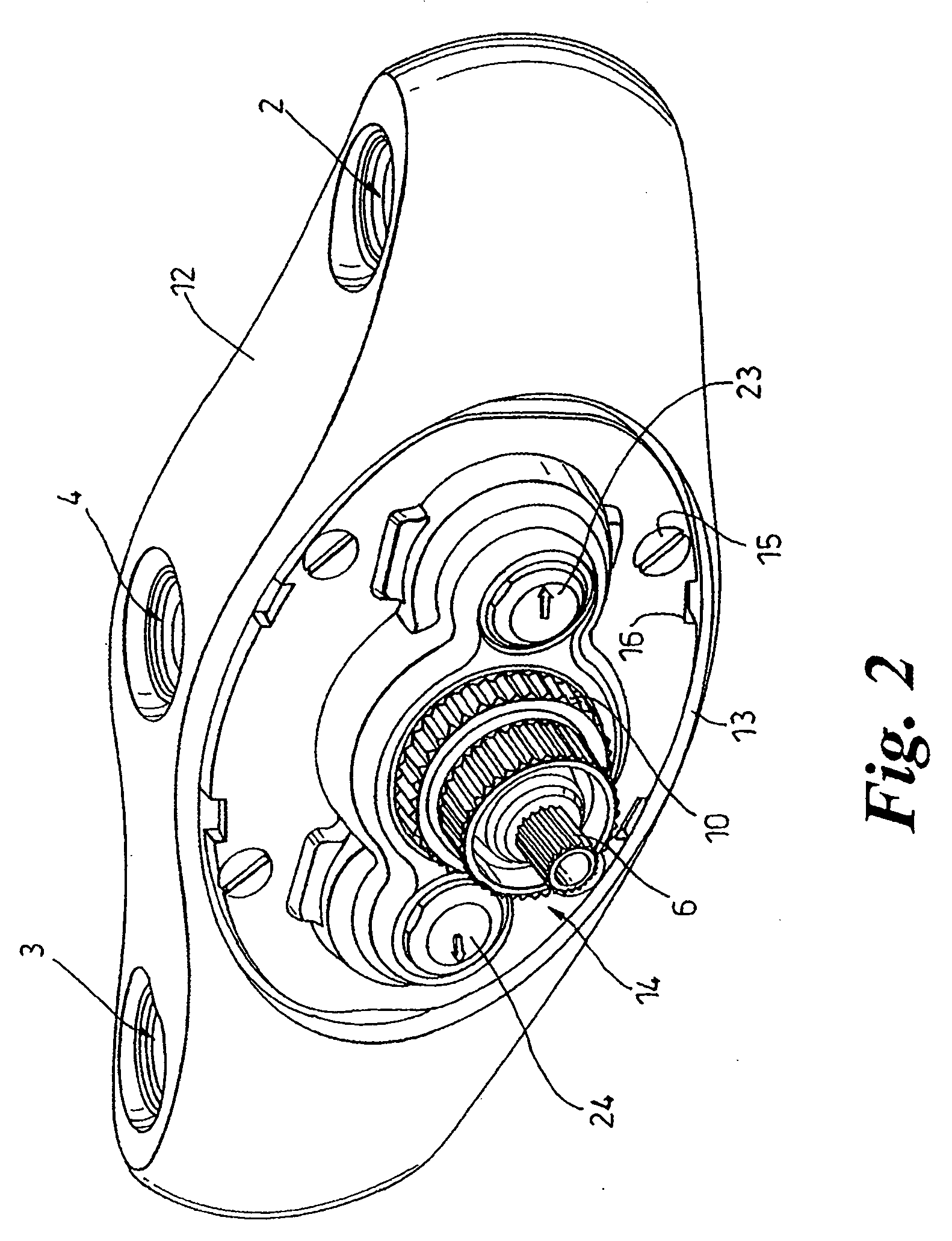
[0137] Referring first to FIGS. 1 to 4 of the accompanying drawings, a thermostatic mixing valve 1 according to the invention is shown. The mixing valve 1 has inlets 2 and 3 for connection to respective supplies of cold and hot water (not shown) and an outlet 4 for discharging temperature controlled water to an ablutionary appliance (not shown) such as a spray fitting for a shower or other washing equipment. In this embodiment, each inlet 2,3 has two ports 2a,2b and 3a,3b at right angles to each other for connecting the valve 1 to supply pipes from above or behind the valve 1. A blanking plug (not shown) is provided for closing each port that is not connected to a supply pipe.

[0138] The valve 1 has a rotatable temperature control knob 5 detachably mounted on a drive spindle 6 of a temperature control mechanism described in more detail later herein. The knob 5 is rotatable relative to a fixed indicator ring 7 for user selection of a range of outlet-water temperatures, for example fro...

second embodiment

[0172] Referring now to FIGS. 5 to 9 of the drawings, there is shown an electronically controlled thermostatic mixing valve 101 according to the present invention. The mixing valve 101 has spaced parallel inlets 102,103 for connection to supplies of hot and cold water (not shown) and two outlets 104,105 for discharging temperature controlled blended water. The outlets 104,105 are spaced apart 180° for selective connection to an ablutionary appliance such as a shower spray fitting.

[0173] The mixing valve 101 may be provided in a range of sizes for different applications. For example, smaller valves may supply a single shower or a group of showers. Larger valves may be connected in a water circulation system to provide a hot water circuit around a building in which the water is maintained at a constant temperature and can be supplied to a large number of appliances at different locations.

[0174] The valve 101 has a cylindrical body 106 with the outlets 104,105 at one end and an openin...

third embodiment

[0207] Referring now to FIGS. 10 to 14 of the accompanying drawings, a thermostatic mixing valve 201 according to the present invention is shown. The valve 201 has inlets 202,203 for connection to supplies of hot and cold water (not shown) and an outlet 204 for discharging temperature controlled water to an ablutionary appliance such as a shower (not shown).

[0208] The valve 201 has a drive spindle 205 for mounting a rotatable temperature control knob (not shown) for user selection of a range of outlet water temperatures, for example from cold to 60° C.

[0209] As best shown in FIG. 11, the valve 201 has a body 206 with a cylindrical bore 207 for reception of a detachable cartridge unit 208 shown in FIGS. 12 and 13.

[0210] The body 206 has an external screw thread 209 at the open end of the bore 207 for engagement of a retainer ring 210 to secure the cartridge unit 208 in the body 206.

[0211] The cartridge unit 208 is located in the correct orientation and prevented from rotating in t...


PUM


Abstract

A thermostatic mixing valve for hot and cold water has two-stage inlet chambers for the hot and cold water flows respectively. The inlet chambers distribute the flows uniformly with respect to porting for admitting the flows to the mixing chamber to reduce asymmetric flow patterns and promote thorough mixing of the flows within the mixing chamber.

Description

[0001] This application is a Continuation of application Ser. No. 11 / 001,242, filed Dec. 1, 2004.FIELD OF THE INVENTION [0002] This invention concerns improvements in or relating to thermostatic mixing valves. The invention has particular, but not exclusive, application to thermostatic mixing valves for water supply installations such as showers. BACKGROUND OF THE INVENTION [0003] Thermostatic mixing valves provide a source of water having a desired temperature and are operable to maintain the desired water temperature substantially constant. Typically, the desired water temperature is obtained by controlling the relative proportions or hot and cold water admitted to a mixing chamber and adjusting the relative proportions to maintain the desired water temperature substantially constant. [0004] The known thermostatic mixing valves employ an actuator responsive to water temperature for adjusting the relative proportions in which the hot and cold water are mixed to maintain the desired...

Claims


Application Information

Patent Timeline
Patent Type & Authority Applications(United States)
IPC IPC(8): G05D23/02F16K11/00G05D23/13
CPCG05D23/1346Y10T137/87652Y10T137/86815
Inventor BECK, NICHOLAS JOHNCONWAY, SEAN PATRICKHAYWARD, BRUCE LEWIN JOHNPEEL, KEVIN TAYLOR
Owner KOHLER MIRA LTD
Why Eureka
Try Eureka