Magnetic sensor element and electronic directional measureing device

a magnetic sensor and electronic directional measuring technology, applied in the field of magnetic sensor elements, can solve the problems of low height, low height, and small size of the portable terminal, and achieve the effect of reducing height and siz

Inactive Publication Date: 2007-09-27
CITIZEN WATCH CO LTD
View PDF8 Cites 39 Cited by
  • Summary
  • Abstract
  • Description
  • Claims
  • Application Information

AI Technical Summary

Benefits of technology

[0038] The magnetic sensor element according to the present invention, even if reduced in size, is capable of detecting geomagnetism, and the electronic directional measuring device according to the present invention can be reduced in height as well as size, and is mountable in a portable terminal even if the same is made up as a triaxial magnetic sensor by disposing the three units of the magnetic sensor elements.

Problems solved by technology

Meanwhile, there has been seen a tendency of the portable terminal being rendered smaller in size as well as thickness, and an electronic device mounted therein is required to be small in size, and low in height.
However, when a user attempts to obtain a direction with using a portable terminal provided with the electronic directional measuring device, which is the biaxial magnetic sensor having the function described as above, the portable terminal being in a tilted state (under a tilted environment), the following problem will occur to the electronic directional measuring device.
Under such an environment as described, the biaxial magnetic sensor as described is incapable of calculating an accurate azimuth.
However, if the element is simply reduced in size, this will render it difficult to make effective magnetic fluxes to be converged.
Then, an excitation current necessary for causing the magnetism sensitive part 111 to undergo magnetization saturation will become considerably large in magnitude, thereby rendering it practically difficult to cause occurrence of the magnetization saturation.
However, it is extremely difficult to reduce the nonmagnetic base 120 into the constricted shape or the like by applying micromachining thereto.

Method used


Image

  • Magnetic sensor element and electronic directional measureing device
  • Magnetic sensor element and electronic directional measureing device
  • Magnetic sensor element and electronic directional measureing device

Examples


Embodiment Construction

A Basic Embodiment of a Magnetic Sensor Element

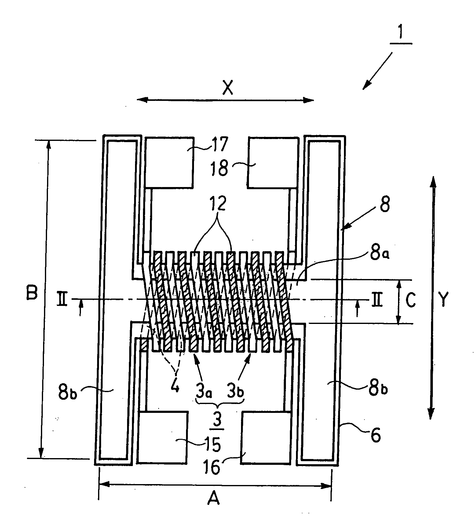
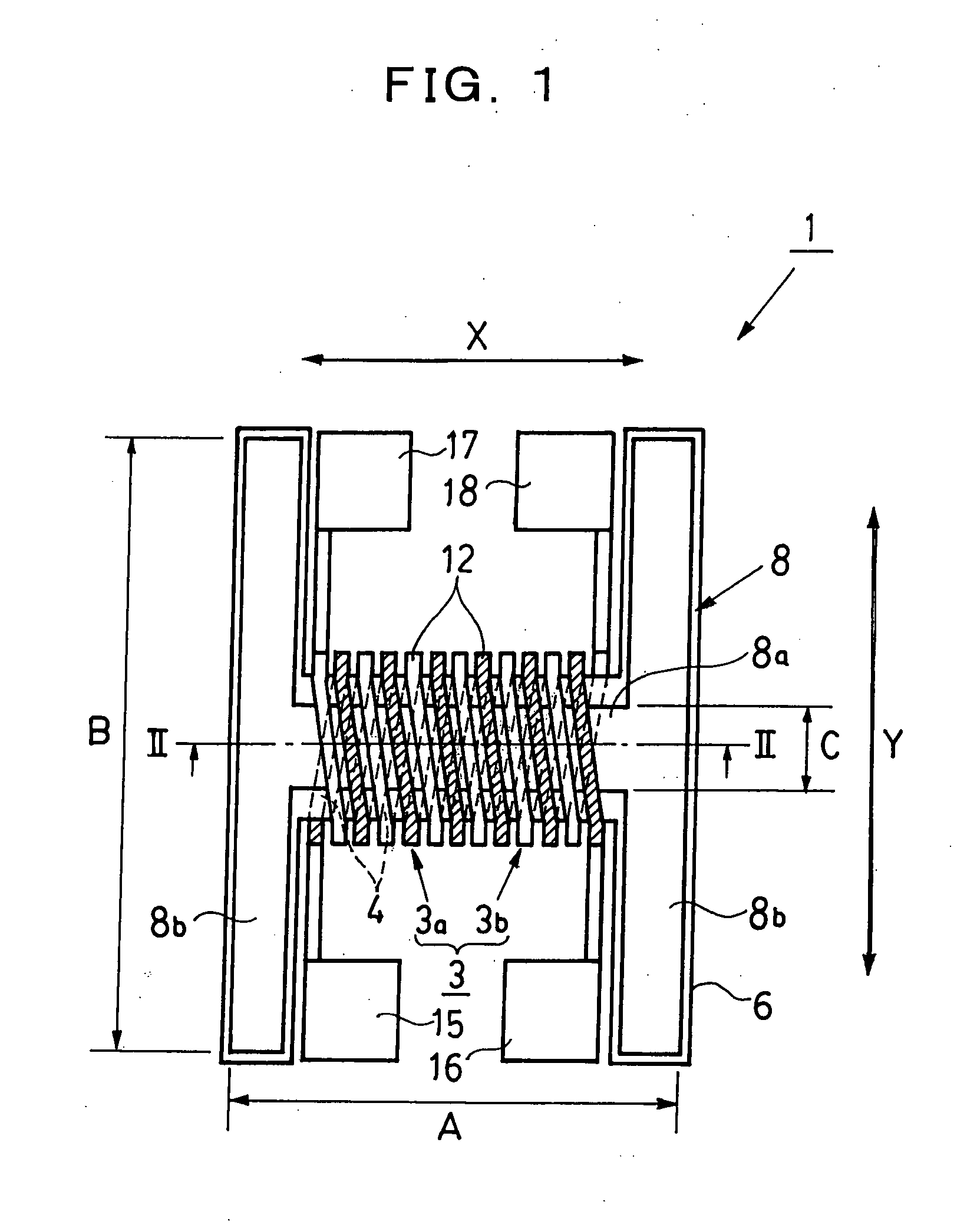
[0052] A magnetic sensor element according to the present invention basically comprises a magnetic core layer made of a soft magnetic material, and a thin-film coil made up of a lower coil layer and an upper coil layer, and the magnetic core layer adopts a structure made up of a magnetism sensitive part positioned at a central part thereof and magnetism collective part positioned at respective ends thereof. A more specific makeup of the embodiment will be described in detail hereinafter with reference to the accompanying drawings.

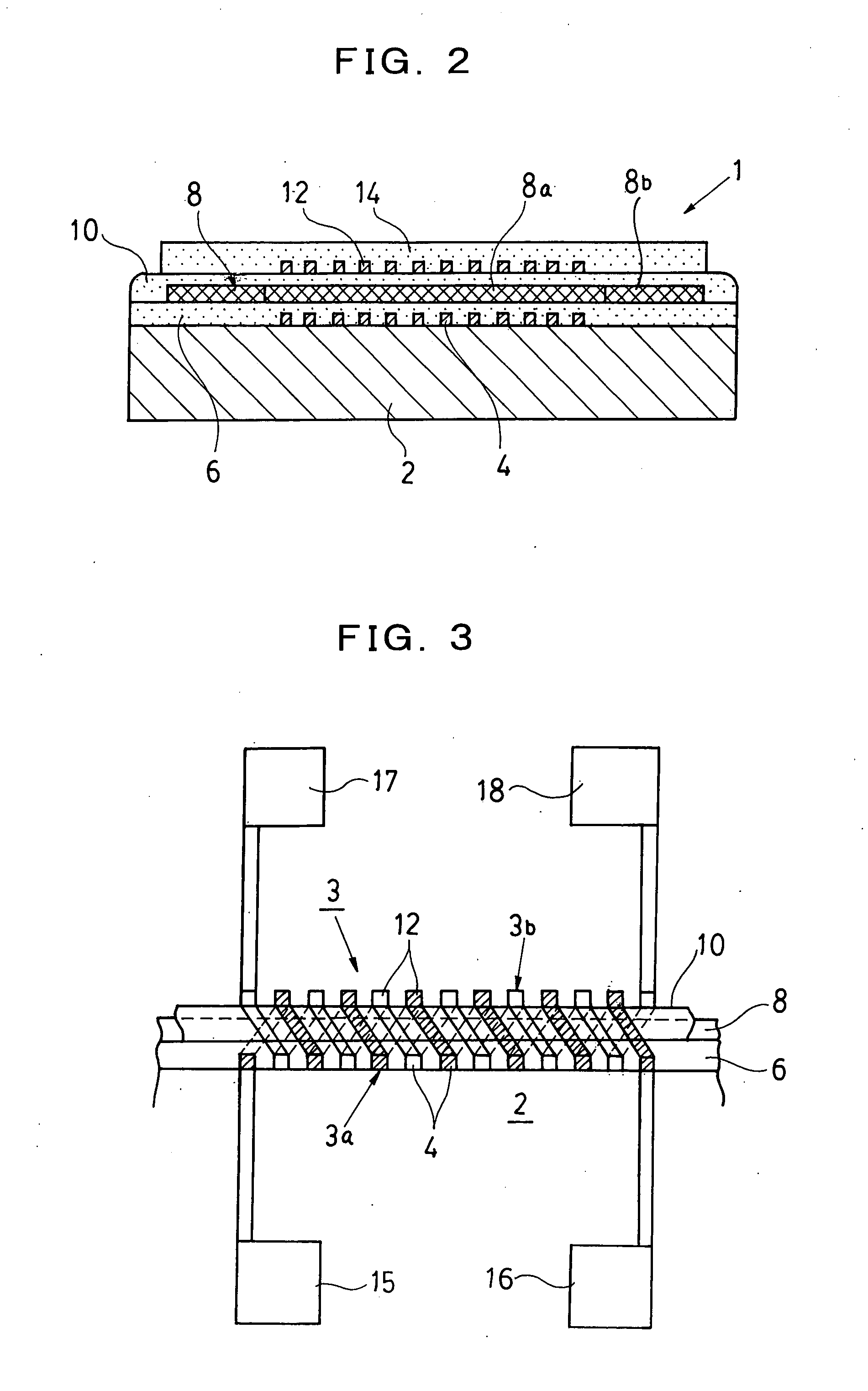
[0053] First, the makeup of the magnetic sensor element according to the basic embodiment of the present invention is described hereinafter. FIG. 1 is a plan view showing the concept of the magnetic sensor element. FIG. 2 is an expanded sectional view of the magnetic sensor element along the line E-E in FIG. 1. Further, the plan view of FIG. 1 shows the magnetic sensor element in a state where a protection fil...


PUM


Abstract

A magnetic sensor element of a flux gate type comprising a magnetism sensitive part (8a) formed by winding a coil (3) around a magnetic core layer (8), and magnetism collective part (8b) for guiding magnetic fluxes to the magnetism sensitive part (8a). Respective central parts of the magnetism collective part (8b) are connected with the respective ends of the magnetism sensitive part (8a). Therefor the magnetic core layer (8) is formed so as to resemble a letter H in planar shape. And the coil (3) of the magnetism collective part (8b) is a thin-film coil comprising a plurality of upper coil thin-films (12) and a plurality of lower coil thin-films (4) formed on an upper surface and a lower surface of the magnetic core layer (8) via insulation layers by connecting together the respective lower coil thin-films (4) and the upper coil thin-films (12), at respective adjacent ends thereof, so as to be sequentially continuous with each other.

Description

BACKGROUND OF THE INVENTION [0001] 1. Field of the Invention [0002] The present invention relates to a magnetic sensor element of a parallel flux gate type, small in size, and an electronic directional measuring device with the magnetic sensor elements mounted therein, and more particularly, to a magnetic sensor element of the flux gate type, small in size, and mountable in a portable terminal, and an electronic directional measuring device provided with three units of the magnetic sensor elements, arranged so as to be orthogonal in orientation to each other. [0003] 2. Description of the Related Art [0004] An electronic directional measuring device has a feature in that a bearing can be electrically detected with the use of a magnetic sensor, and so forth. The electronic directional measuring device is generally made up by disposing a plurality of the magnetic sensor elements thereon. The magnetic sensor elements of the parallel flux gate type, like this, exhibit a linear output aga...

Claims


Application Information

Patent Timeline
Patent Type & Authority Applications(United States)
IPC IPC(8): G01R33/04
CPCG01R33/04G01R33/0206
Inventor SATOH, MASAHIRO
Owner CITIZEN WATCH CO LTD
Why Eureka
Try Eureka