Batteryless tire inflation pressure detecting apparatus having minimum influence on environment

a tire inflation and pressure detection technology, applied in the direction of tire measurement, vehicle components, transportation and packaging, etc., can solve the problem of influencing the device by strong nois

Inactive Publication Date: 2007-09-27
DENSO CORP +1
View PDF7 Cites 10 Cited by
  • Summary
  • Abstract
  • Description
  • Claims
  • Application Information

AI Technical Summary

Benefits of technology

[0061] With the above configuration, it is also possible to reduce the possibility of the first and second radio waves exerting undesirable influences on electric or electronic devices provided on the vehicle.

Problems solved by technology

Accordingly, when the radio waves for electric power charge reach and intersect in an area where automotive electric or electronic devices, such as a radio, an ECU, and a keyless entry system, are provided, they may produce strong noises that influence those devices.

Method used


Image

  • Batteryless tire inflation pressure detecting apparatus having minimum influence on environment
  • Batteryless tire inflation pressure detecting apparatus having minimum influence on environment
  • Batteryless tire inflation pressure detecting apparatus having minimum influence on environment

Examples


first embodiment

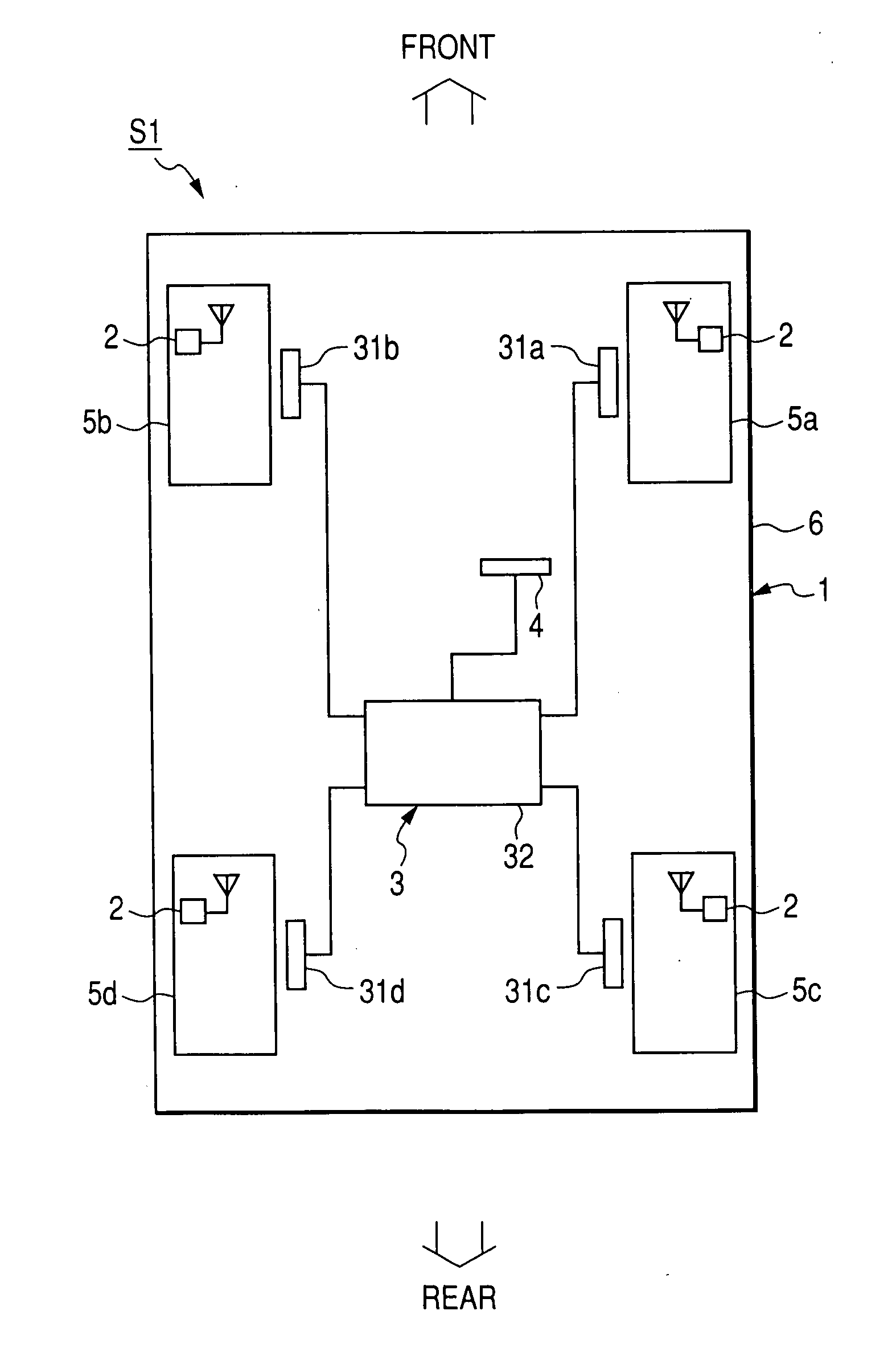
[0084]FIG. 1 shows the overall configuration of a batteryless, direct-type tire inflation pressure detecting apparatus S1 according to the first embodiment of the invention.

[0085] The tire inflation pressure detecting apparatus S1 is installed to a vehicle 1 which includes four wheels 5a-5d (i.e., the FR wheel 5a, the FL wheel 5b, the RR wheel 5c, and the RL wheel 5d).

[0086] As shown in FIG. 1, the tire inflation pressure detecting apparatus S1 includes four wheel-side transceivers 2, a body-side transceiver 3, and a warning device 4.

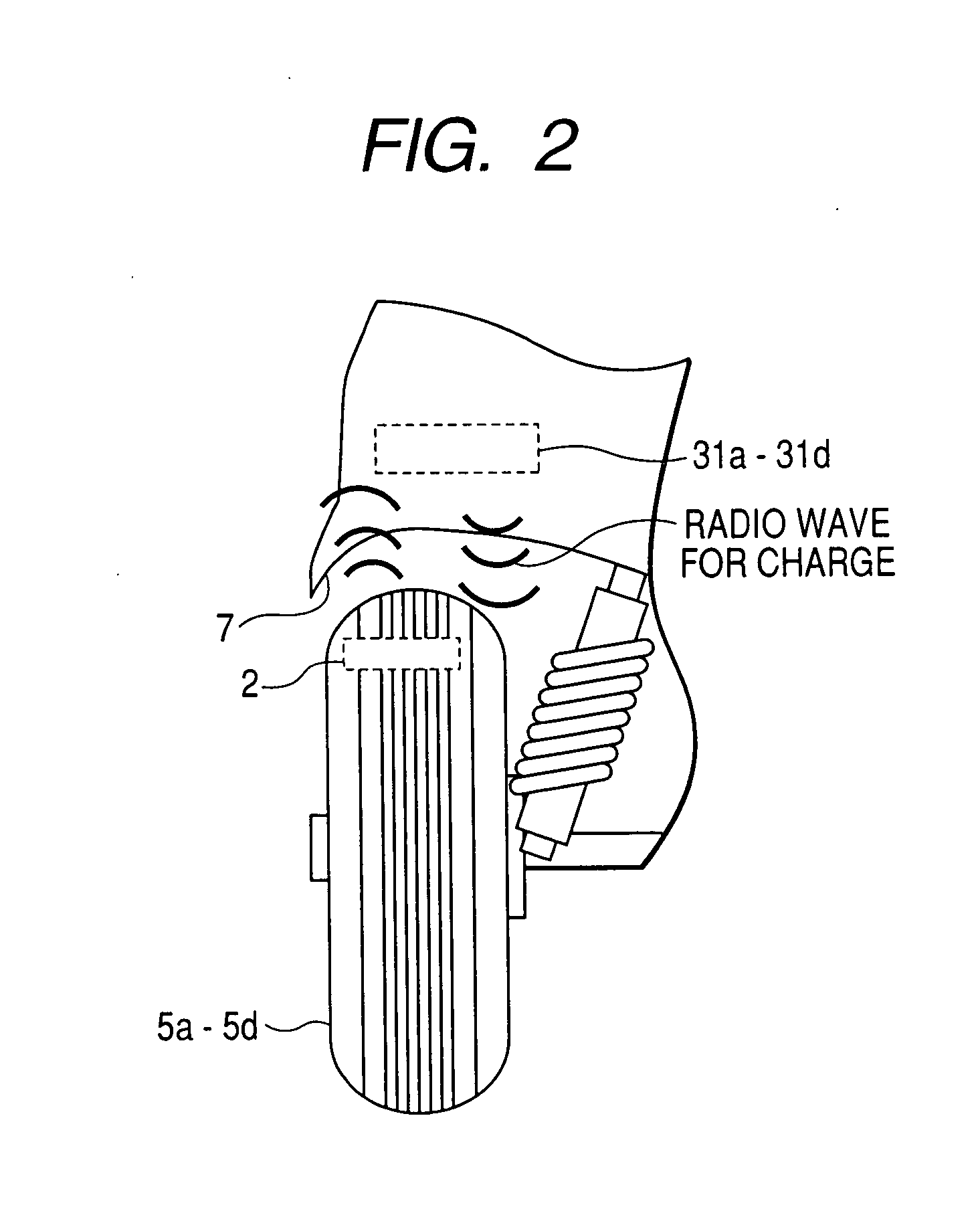
[0087] Referring further to FIG. 2, each of the wheel-side transceivers 2 is mounted on a corresponding one of the four wheels 5a-5d of the vehicle 1, so as to have association with a tire fitted on the corresponding wheel.

[0088] Each of the wheel-side transceivers 2 works to sense the inflation pressure of the associated tire and transmit a frame that contains tire pressure information indicative of the sensed inflation pressure of the associated t...

second embodiment

[0137] This embodiment illustrates a control of transmission of the radio waves for electric power charge which is different from that of the previous embodiment.

[0138] As described previously, in the first embodiment, there are no time intervals between the ON periods of the radio waves transmitted through the FR and RL antennas 31a and 31d and the succeeding ON periods of the radio waves transmitted through the FL and RR antennas 31b and 31c. In other words, the end times of the ON periods of the radio waves transmitted through the FR and RL antennas 31a and 31d exactly coincide with the start times of the succeeding ON periods of the radio waves transmitted through the FL and RR antennas 31b and 31c.

[0139] In comparison, referring to FIG. 8, in the present embodiment, there are provided time intervals between the ON periods of the radio waves transmitted through the FR and RL antennas 31a and 31d and the succeeding ON periods of the radio waves transmitted through the FL and RR...

third embodiment

[0143] This embodiment illustrates a control of transmission of the radio waves for electric power charge which is different from those of the previous embodiments.

[0144] As described previously, in the first and second embodiments, the ON periods of the radio waves transmitted through the FR and RL antennas 31a and 31d do not overlap with those of the radio waves transmitted through the FL and RR antennas 31b and 31c.

[0145] In comparison, referring to FIG. 9, in the present embodiment, the ON periods of the radio waves transmitted through the FR and RL antennas 31a and 31d partially overlap with those of the radio waves transmitted through the FL and RR antennas 31b and 31c.

[0146] In this case, during the overlapping part of the ON periods, the radio waves intersect in the areas A-D shown in FIG. 4, and the resultant waves thereof may become noises for automotive devices disposed on those area.

[0147] However, compared to the case where the ON periods of the radio waves transmit...


PUM


Abstract

A batteryless tire inflation pressure detecting apparatus includes, on the body of a vehicle, antennas and a transmitter transmitting radio waves through the antennas. The apparatus also includes, on each wheel of the vehicle, a pressure sensor sensing the pressure of a tire, a transceiver, and a charging unit powering the pressure sensor and the transceiver. The charging unit is charged with electric power induced by a corresponding one of the radio waves received by the transceiver. The apparatus further includes, on the body of the vehicle, a receiver receiving pressure signals transmitted by the transceivers, a pressure determiner determining the pressures of the tires based on the pressure signals, and a controller. To minimize influence of the radio waves on neighboring devices, the controller controls the transmitter so that least two of the radio waves are transmitted at different times, or at the same with a phase difference therebetween.

Description

CROSS-REFERENCE TO RELATED APPLICATION [0001] This application is based on and claims priority from Japanese Patent Application No. 2006-78812, filed on Mar. 22, 2006, the content of which is hereby incorporated by reference into this application. BACKGROUND OF THE INVENTION [0002] 1. Technical Field of the Invention [0003] The present invention relates generally to tire inflation pressure detecting apparatuses and wireless electric power charging systems. More particularly, the invention relates to a batteryless, direct-type tire inflation pressure detecting apparatus for a vehicle which is based on a transponder method and has minimum influence on electric or electronic devices provided on the vehicle. [0004] 2. Description of the Related Art [0005] A conventional direct-type tire inflation pressure detecting apparatus includes at least a transmitter and a receiver. [0006] The transmitter is directly installed to a wheel of a vehicle and includes a pressure sensor working to sense...

Claims


Application Information

Patent Timeline
Patent Type & Authority Applications(United States)
IPC IPC(8): B60C23/00
CPCB60C23/0408B60C23/0464B60C23/0413
Inventor SAITOU, TAKASHITAKAOKA, AKIRAWATABE, NOBUYASAITO, HIDEKIKUNO, TOMOHIRO
Owner DENSO CORP
Why Eureka
Try Eureka