Angular velocity sensor device

a sensor device and angular velocity technology, applied in the direction of turn-sensitive devices, acceleration measurement using interia forces, instruments, etc., can solve the problems of inability to provide a complete solution, fatal risk of self-resonance not occurring, and inability to obtain high detection accuracy

Active Publication Date: 2006-02-21
DENSO CORP
View PDF5 Cites 7 Cited by
  • Summary
  • Abstract
  • Description
  • Claims
  • Application Information

AI Technical Summary

Benefits of technology

[0021]If an angular velocity sensor device is adjusted by this adjustment method, the influence of noise signals entering the monitor electrodes from the driving electrodes can be kept to a minimum and the weight part can be made to oscillate stably in the first direction.

Problems solved by technology

Although the methods described above do provide some reduction in the distortion resulting from the noise signals, they do not provided a complete solution.
Even if the noise signals affecting the detection electrodes are reduced, if the oscillation of the weight part is unstable due to the noise signals affecting the monitor signals, high detection accuracy cannot be obtained.
Further, when the amplitude of the noise signals is large compared to the true monitor signals, i.e. the signals generated by the oscillation of the weight part in the X direction, there is a fatal risk of self-resonance not occurring and the device therefore not functioning as an angular velocity sensor.

Method used


Image

  • Angular velocity sensor device
  • Angular velocity sensor device
  • Angular velocity sensor device

Examples


Embodiment Construction

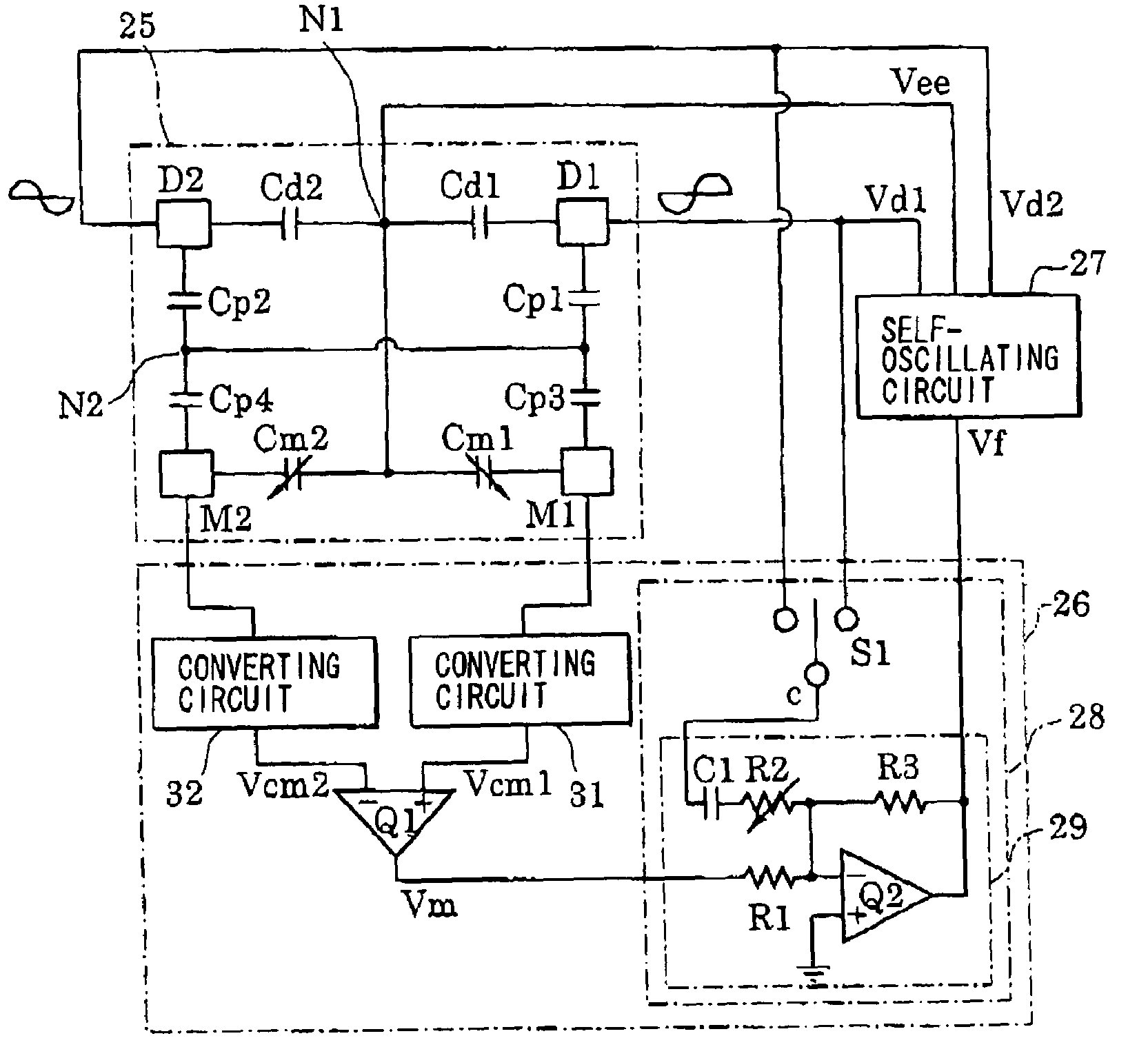
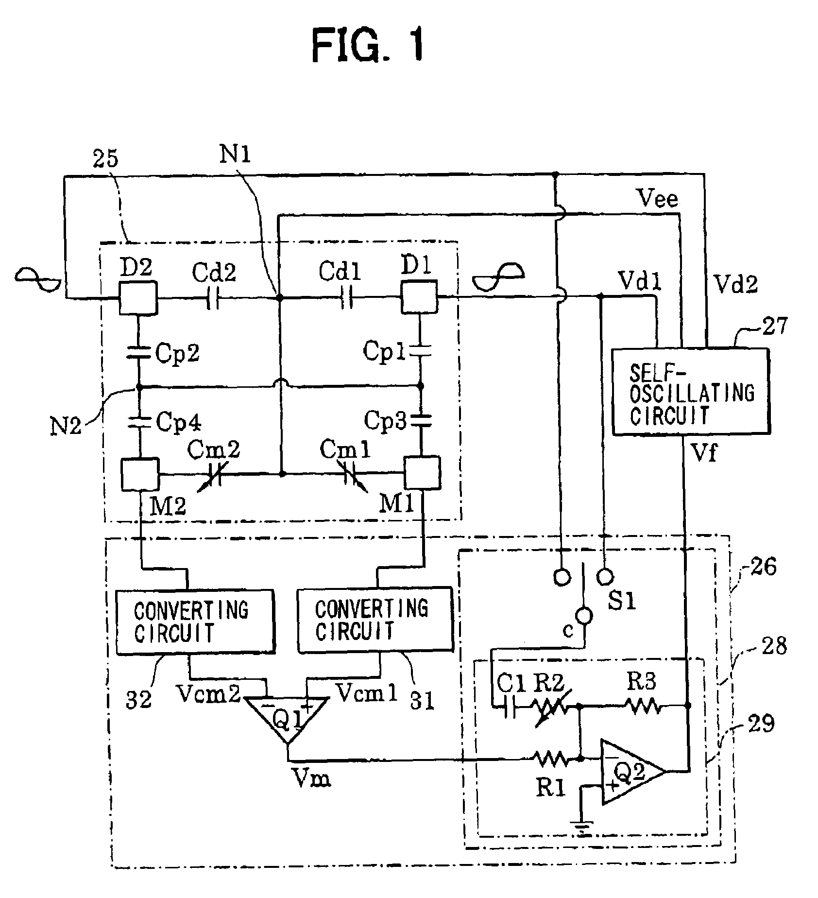
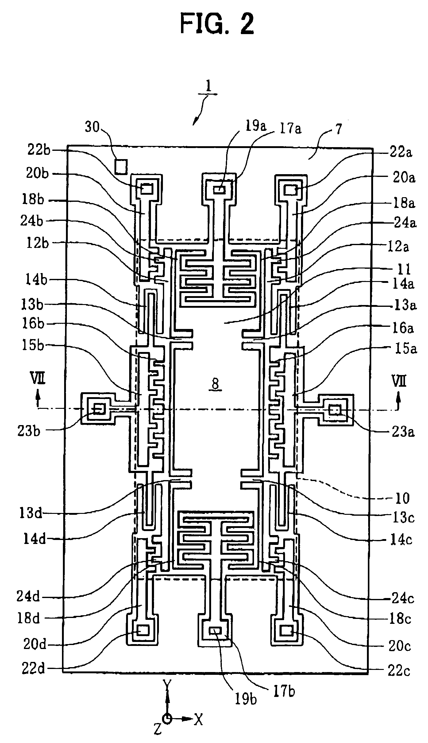
[0031]An electrostatically-driven static capacitance detection type angular velocity sensor device according to a preferred embodiment of the invention will now be described with reference to FIGS. 1–5 and 7. The angular velocity sensor device is comprised of an electrostatically-driven static capacitance detection type angular velocity sensor (angular velocity sensor) and control circuits such as a sensor driving circuit and a signal processing circuit. FIG. 2 is a plan view of one example of this angular velocity sensor, and FIG. 7 is a sectional view along line VII–VIX in FIG. 2.

[0032]Referring to FIG. 7, the angular velocity sensor 1 is formed using an SOI substrate 5 comprised of an oxide film 3 on the surface of a first silicon substrate 2 and a second silicon substrate 4 affixed to the oxide film 3. The SOI substrate 5 is fixed by means of an adhesive or the like to a circuit chip 6 on which control circuits such as a driving circuit and a signal processing circuit are formed...


PUM


Abstract

An angular velocity sensor device includes a switch (S1) for selecting a first or second driving signal mutually opposite in phase applied to driving electrodes (D1, D2) to oscillate a weight part (8) in a first direction. An adding circuit (29) adjusts the amplitude of the driving signal selected and adds it to a monitor signal reflecting the oscillating state of the weight part (8). A noise signal component appearing in the output signal of the adding circuit (29) is adjusted to a minimum and the output signal is supplied as a feedback signal to a self-oscillating circuit (27) for reducing the noise signal influence on the oscillating drive of the weight part.

Description

CROSS REFERENCE TO RELATED APPLICATION[0001]This application is based upon, claims the benefit of priority of, and incorporates by reference the contents of Japanese Patent Application No. 2003-90970 filed on Mar. 28, 2003.FIELD OF THE INVENTION[0002]This invention relates to an angular velocity sensor device that effectively reduces noise signals from distorting sensor measurements.BACKGROUND OF THE INVENTION[0003]An electrostatically-driven static capacitance detection type angular velocity sensor conventionally includes a weight part (or oscillator) disposed on a semiconductor substrate. The weight part is formed on the semiconductor substrate and is able to oscillate in mutually perpendicular first and second directions. The angular velocity sensor also includes driving electrodes for receiving a driving signal to oscillate the weight part periodically in the first direction, monitor electrodes for monitoring static capacitance variations based on the oscillation of the weight p...

Claims


Application Information

Patent Timeline
Patent Type & Authority Patents(United States)
IPC IPC(8): G01P9/04G01C19/56G01C19/5719G01C19/5726G01C19/5755
CPCG01C19/5719
Inventor ITO, HAJIME
Owner DENSO CORP
Why Eureka
Try Eureka