Apparatus and method for tracing position and direction of target object through RF signal

a technology of target objects and antennae, applied in the field of antennae and a method for tracing the position and direction of a target object through a radio frequency (rf) signal, can solve the problems of increasing operation errors, extreme sensitive lighting changes of position tracking systems, and inability to use gps indoors, so as to achieve the effect of reducing the influence of surrounding environments and facilitating tracing

Inactive Publication Date: 2008-09-18
ELECTRONICS & TELECOMM RES INST
View PDF11 Cites 9 Cited by
  • Summary
  • Abstract
  • Description
  • Claims
  • Application Information

AI Technical Summary

Benefits of technology

[0013]An aspect of the present invention provides an apparatus and a method for tracing position and direction of a target object with an RF signal transceiver, such that easier tracing can be achieved with the minimum influence of surrounding environments.

Problems solved by technology

However, the GPS basically includes various operative errors, and the operative errors increase due to a variety of factors such as arrangements of satellites, weather conditions, buildings, and forests, which may affect a GPS signal reception.
Most importantly, The GPS may not be feasible indoors because there are limitations in receiving a GPS signal.
However, this position tracking system is extremely sensitive to a lighting change.
As a result, this may have a limitation in searching for a target object, because it is difficult to recognize direction, position, and a size change of the target object in a dark environment.
However, this position tracking system is especially sensitive to surrounding noise because of its operating property that utilizes a sound source, and thus may not be appropriately functioned in general environments.

Method used


Image

  • Apparatus and method for tracing position and direction of target object through RF signal
  • Apparatus and method for tracing position and direction of target object through RF signal
  • Apparatus and method for tracing position and direction of target object through RF signal

Examples


Embodiment Construction

[0025]Preferred embodiments of the present invention will be described below in more detail with reference to the accompanying drawings. The present invention may, however, be embodied in different forms and should not be constructed as limited to the embodiments set forth herein. Rather, these embodiments are provided so that this disclosure will be thorough and complete, and will fully convey the scope of the present invention to those skilled in the art.

[0026]Accordingly, in some embodiments, well-known processes, well-known device structures, and well-known techniques will not be described in detail to avoid ambiguous interpretation of the present invention. Like reference numerals refer to like elements throughout.

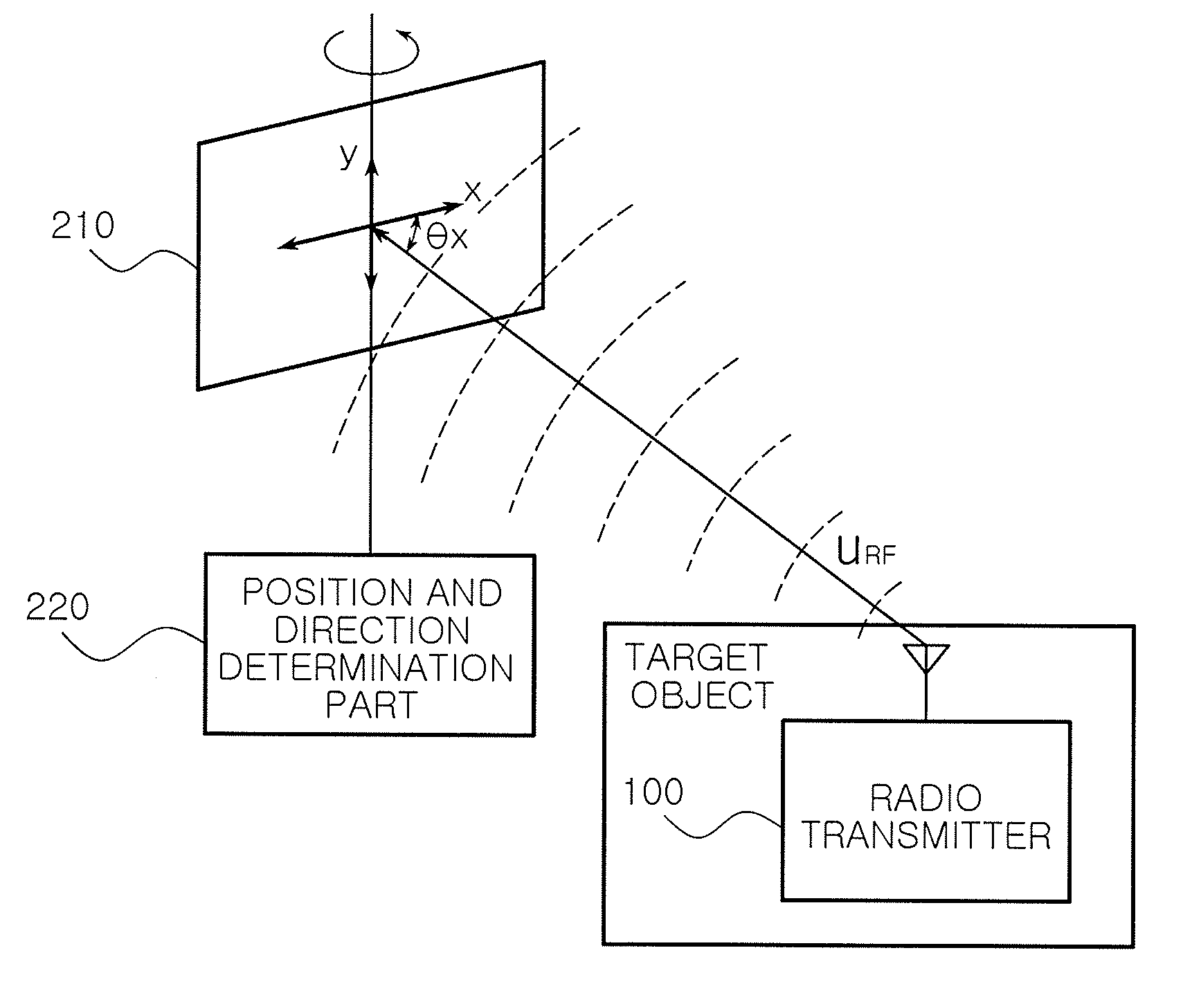
[0027]FIG. 1 is a view of an apparatus for tracing position and direction of an RF transceiver according to one embodiment of the present invention.

[0028]Referring to FIG. 1, the apparatus for tracing position and direction of an RF transceiver has a plate-shaped and ...


PUM


Abstract

An apparatus for tracing position and direction of a target object through an RF signal includes two loop antennas and a position and direction determination part. The two loop antennas receive the RF signal transmitted from the target object and are perpendicularly coupled to each other. The position and direction determination part calculates two RF signal intensities received through the respective two loop antennas for comparison, and then determines that the target object transmitting an RF signal is placed in a center direction between the two loop antennas if the two RF signal intensities are the same, and otherwise determines that the target object is placed in a front direction of the loop antenna having a relatively higher RF signal intensity.

Description

CROSS-REFERENCE TO RELATED APPLICATIONS[0001]This application claims the priority of Korean Patent Application No. 10-2007-0025034, filed on Mar. 14, 2007, in the Korean Intellectual Property Office, the disclosure of which is incorporated herein by reference.BACKGROUND OF THE INVENTION[0002]1. Field of the Invention[0003]The present invention relates to an apparatus and a method for tracing position and direction of a target object, and more particularly, to an apparatus and a method for tracing position and direction of a target object through a radio frequency (RF) signal.[0004]This work was supported by the IT R&D program of MIC / IITA [2005-S-092-02, USN-based Ubiquitous Robotic Space Technology Development][0005]2. Description of the Related Art[0006]In general, an apparatus for tracing position and direction of a target object has been studied in various fields to provide more services to human life, and its technical development is being already in great progress.[0007]One of ...

Claims


Application Information

Patent Timeline
Patent Type & Authority Applications(United States)
IPC IPC(8): G01S13/06G01S19/17G01S19/34
CPCG01S13/06G01S13/02G01S5/0252G01S5/021G01S11/06
Inventor KIM, MYUNG SIKCHONG, NAK YOUNGKIM, HYUNG WOOK
Owner ELECTRONICS & TELECOMM RES INST
Why Eureka
Try Eureka