Superconducting NMR resonators with macroscopically homogeneous superconductor distribution

a superconductor distribution and superconductor technology, applied in the direction of magnetic resonance, acoustic wave reradiation, measurement devices, etc., can solve the problem that the nmr spectrum no longer has a significant influen

Inactive Publication Date: 2003-08-12
BRUKER SWITZERLAND AG
View PDF11 Cites 8 Cited by
  • Summary
  • Abstract
  • Description
  • Claims
  • Application Information

AI Technical Summary

Problems solved by technology

This uniform distribution of the dipole moments which are produced by currents induced in the superconductor, produces a nearl...

Method used


Image

  • Superconducting NMR resonators with macroscopically homogeneous superconductor distribution
  • Superconducting NMR resonators with macroscopically homogeneous superconductor distribution
  • Superconducting NMR resonators with macroscopically homogeneous superconductor distribution

Examples


first embodiment

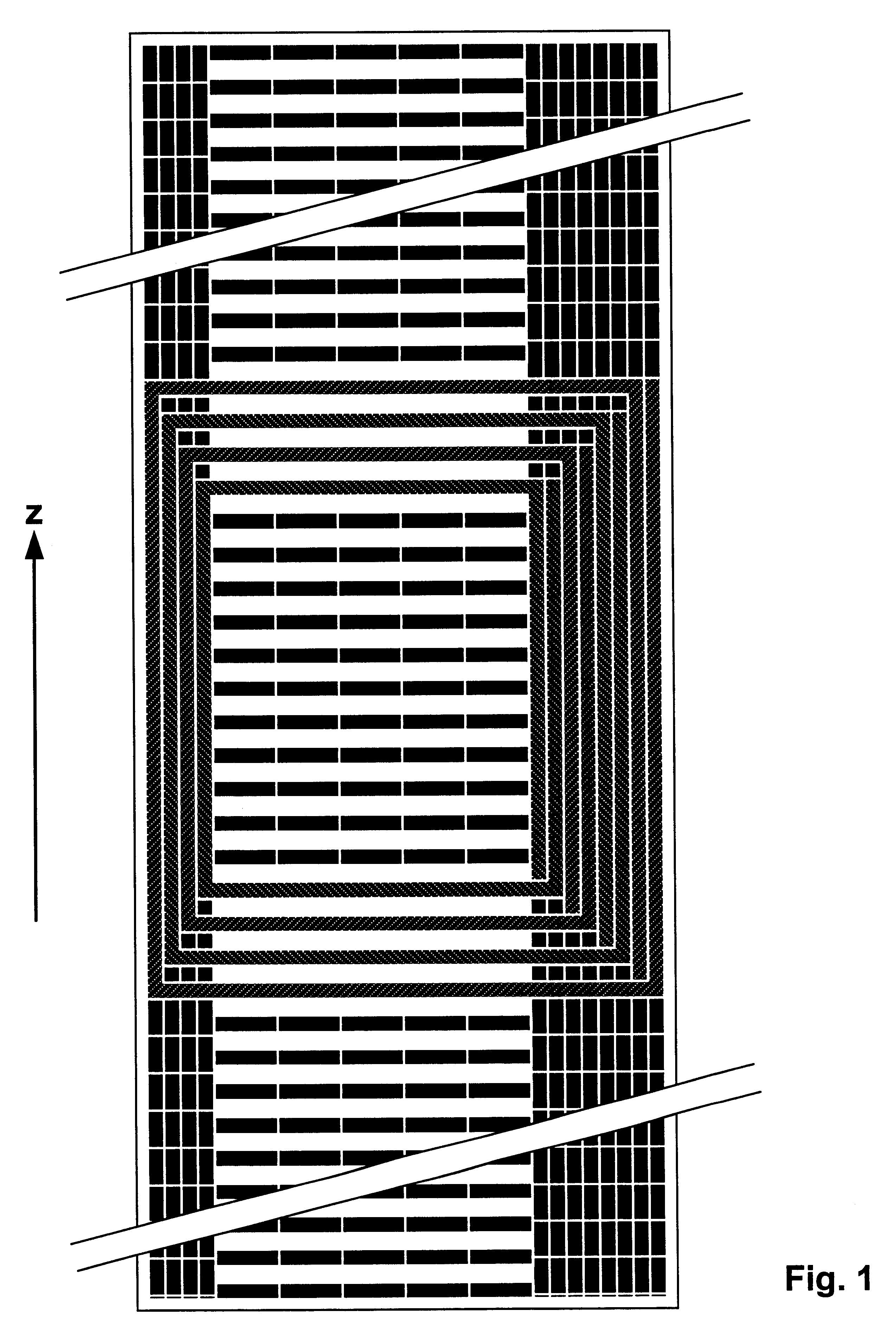
In the inventive idea, the first Z structure consists of strips parallel to the B.sub.0 field followed by a second structure with strips perpendicular to the B.sub.0 field, which is again followed by a third structure with strips parallel to the B.sub.0 field. FIG. 10a shows an example thereof, wherein the three Z structures are selected such that an RF resonator of the type of FIG. 10a in patent [6] can be produced therefrom. The region of the Z structures from which the RF resonator is to be produced is hatched in FIG. 10a (region 7a). The predominantly field-generating conductors are produced from the left Z structure 8a which is the closest to the measuring sample. The upper and lower transverse conductors are produced from the central structure 9a and the capacitive portions are produced from the right structure 10a. The right conductor structure 10a has twice as many conductors as the left conductor structure 8a to permit production of the capacitive portions.

The principal pro...

second embodiment

For this reason, in the inventive idea, the central conductor structure 9a of FIG. 10a is replaced by the more transparent conductor structure 9b of FIG. 10b. Carrying out of the above-described transformation produces the structure of FIG. 12b which is substantially more transparent for RF field lines and therefore has better RF properties.

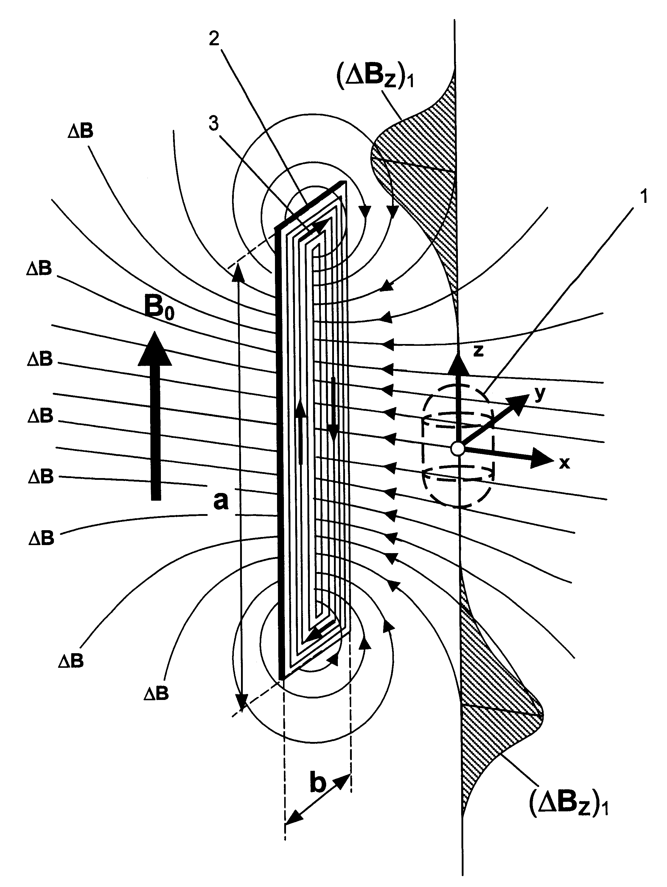
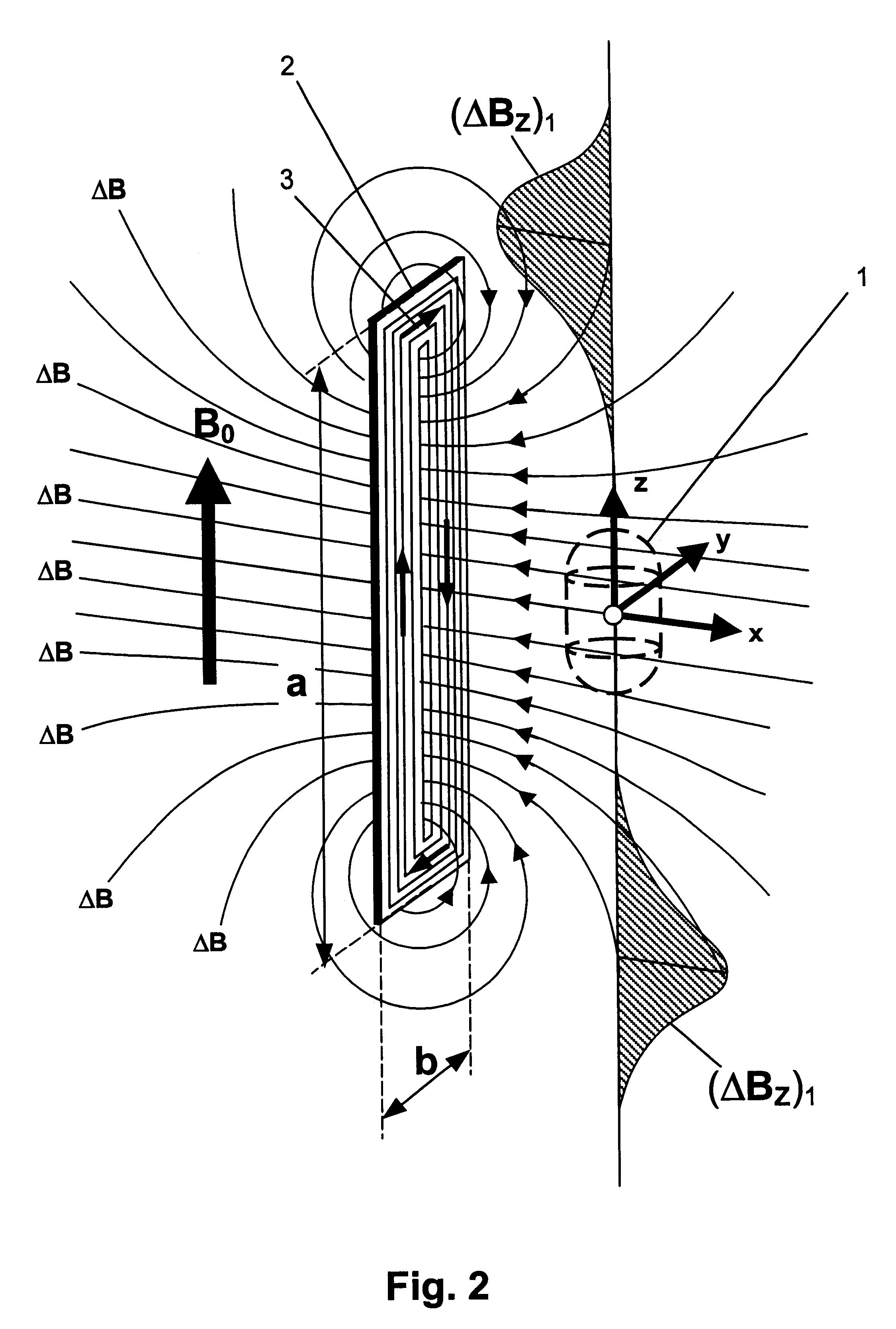
Examination of the two above-described embodiments for remaining error sources produces the two following findings: 1. The disturbing external field which acts on the superconductor must be sufficiently small that the working point is still within the linear region of the magnetization curve, i.e. there is a linear relation between current in the superconductor and disturbing field. If this is not the case, a possible anisotropy of the superconductor must be taken into consideration. Anisotropy means that currents which are parallel to the B.sub.0 field have a different critical current density than those perpendicular to the B.sub.0 field. This ...

third embodiment

Since mainly the anisotropy of the superconductor can produce significant disturbances, the inventive idea presents a variant which omits rotation or displacement of current paths. Three Z structures are also used in this case. The two outer structures are formed with inclined strips according to FIG. 9f and the central one with horizontal strips according to FIG. 9c. The two outer conductor structures have the advantage that a portion of the conductors produce a galvanically coherent structure which extends in the z direction and at the same time permits connections at the edges of the two conductor structures. These connection possibilities permit direct connection to the horizontal strips of the central conductor structure without requiring previous rotation or displacement of current paths.

FIG. 13 shows an example thereof, wherein the conductor structures are selected such that an NMR resonator of the type of FIG. 2c in the patent [8] can be produced. The RF resonator has three ...


PUM


Abstract

An NMR resonator for receiving RF signals at desired resonance frequencies from a measuring sample in a volume under investigation disposed about a coordinate origin (x,y,z=0), with a means for producing a homogeneous magnetic field B.sub.0 in the direction of a z axis, wherein superconducting conductor structures are disposed between z=-.vertline.z.sub.1.vertline. and z=+.vertline.z.sub.2.vertline. on a surface which is translation-invariant (=z-invariant) in the z direction at a radial separation from the measuring sample, is characterized in that a compensation arrangement is additionally provided on the z-invariant surface, which extends to values of at least +.vertline.z.sub.2.vertline.+0.5.vertline.r.vertline.>z> -.vertline.z.sub.1.vertline.-0.5.vertline.r.vertline., wherein .vertline.r.vertline. is the minimum separation between the measuring sample and the compensation arrangement, wherein the compensation arrangement comprises further superconducting conductor structures which are RF-decoupled from the RF resonator, with the conductor structures of the compensation arrangement and of the RF resonator being composed of individual surface sections ("Z-structures") which comprise superconducting structures and are disposed in the z-invariant surface to each extend along the entire length in the z direction of the conductor structures of the compensation arrangement and of the RF resonator, those superconducting structures being disposed such that decomposition of the surface of the Z structures into a plurality of small equally sized surface elements and application of a homogeneous test magnetic field along the surface normal of each surface element for all surface elements which differ only with respect to their z position, induces a magnetic dipole moment of the same strength. In this manner, the disturbing influence caused by magnetization of the superconductor is very well compensated for.

Description

This application claims Paris Convention priority of DE 101 50 131.5 filed Oct. 11, 2001 the complete disclosure of which is hereby incorporated by reference.BACKGROUND OF THE INVENTIONThe invention concerns an NMR (nuclear magnetic resonance) resonator device with at least one RF (radio frequency) resonator for emitting and / or receiving RF signals at one or more desired resonance frequencies to and / or from a measuring sample in an investigational volume, disposed about a coordinate origin (x,y,z=0), of an NMR apparatus with a means for producing a homogeneous magnetic field B.sub.0 in the direction of a z axis, wherein superconducting conductor structures of the RF resonator, which act inductively and partially also capacitively, are disposed between z=-.vertline.z.sub.1.vertline. and z=+.vertline.z.sub.2.vertline. substantially on a surface which is translation-invariant (=z-invariant) in the z direction at a radial (x,y) separation from the measuring sample.An arrangement of this...

Claims


Application Information

Patent Timeline
IPC IPC(8): G01R33/34G01R33/32
CPCG01R33/34061G01R33/34023G01R33/34092
Inventor MAREK, DANIEL
Owner BRUKER SWITZERLAND AG
Why Eureka
Try Eureka