Pattern matching system

a pattern matching and pattern technology, applied in the field of pattern matching systems, can solve problems such as difficulty in accurately carrying out pattern matching, and achieve the effect of accurate carrying out pattern matching and wide variation in brightness

Inactive Publication Date: 2007-09-27
RICOH IMAGING COMPANY
View PDF7 Cites 12 Cited by
  • Summary
  • Abstract
  • Description
  • Claims
  • Application Information

AI Technical Summary

Benefits of technology

[0005]Therefore, an object of the present invention is to provide a pattern matching system that accurately carries out the pattern matching for images with a wide variation in brightness.

Problems solved by technology

In such a pattern matching method, it is difficult to carry out the pattern matching accurately when the brightness of the images varies substantially.

Method used


Image

  • Pattern matching system
  • Pattern matching system
  • Pattern matching system

Examples


first embodiment

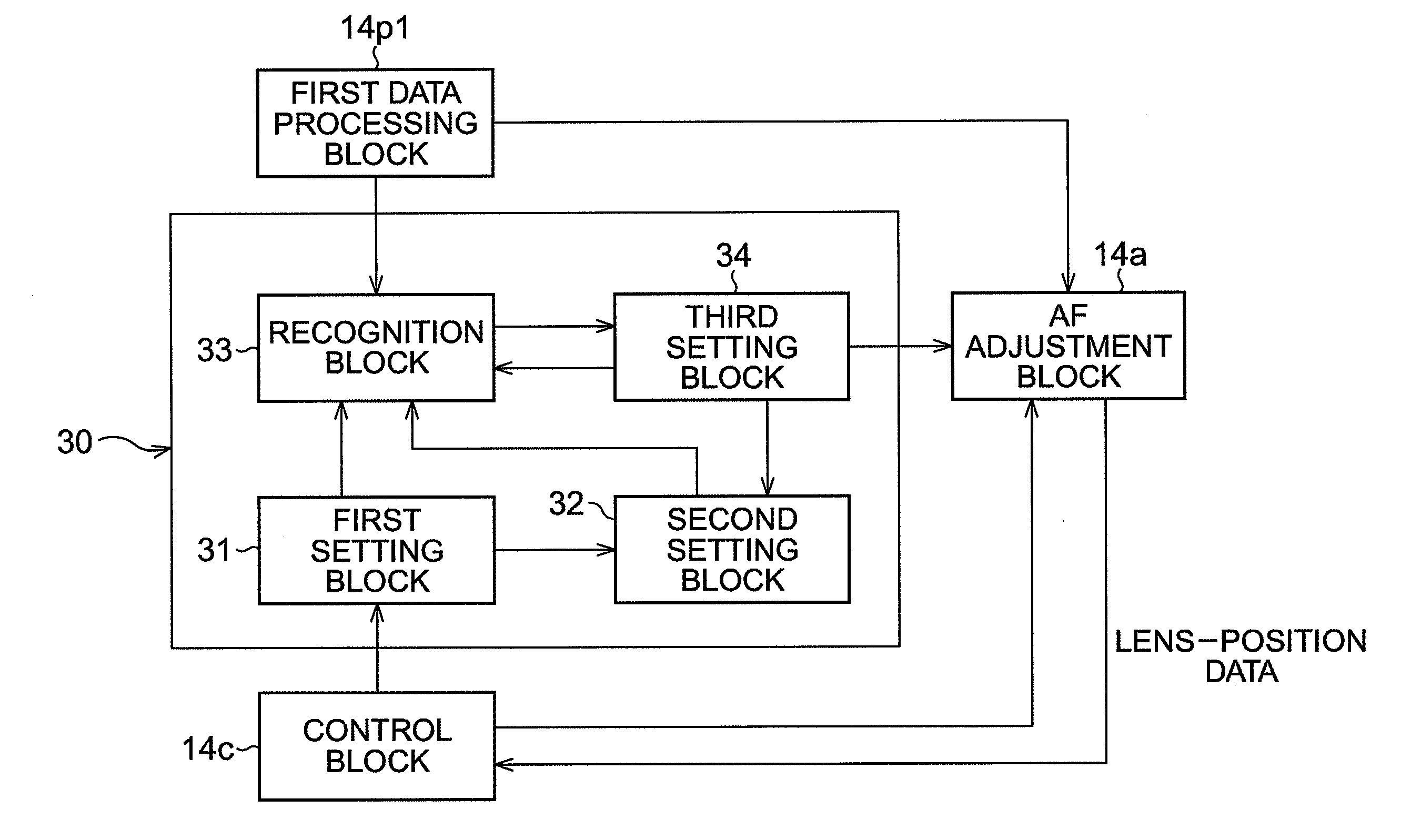
[0102]In the above first embodiment, the signal component used for the pattern matching can be changed to either the singular green signal component, or the aggregate of the red, green, and blue signal components, according to the amplification ratio by the AFE 13 based on the brightness of the object.

[0103]In general, the accuracy of pattern matching can be improved by using many different color signal components. On the other hand, when the signal level of the pixel signal prior to the amplification is low because of a low amount of light received by a pixel 12p, the S / N is also decreased accordingly. In such a case, the accuracy of pattern matching may deteriorate by using many different color signal components.

[0104]It is general knowledge for a prior digital camera to lower an amplification ratio when an optical image of an object is bright and to raise the amplification ratio when the optical image is dark. So, by changing the color signal components used for the pattern match...

second embodiment

[0121]In the second embodiment, when the amplification ratio is less than the first threshold value, the Y and Cr / Cb are used for the pattern matching. However, the pattern matching may be carried out using the Y and only one of either the Cr or Cb.

[0122]For pattern matching, only the green signal component is used when the amplification ratio is greater than the first threshold value, and the red, green, and blue signal components are used when the amplification ratio is less than the first threshold value, in the first embodiment. However, the type of the signal component used for pattern matching may be changed according to the amplification ratio.

[0123]For example, when the amplification ratio is great, the red, green, and blue signal components can be used for pattern matching. Generally, when the amplification ratio is great, it is preferable to use a singular signal component for the pattern matching as described in the above embodiments. However, if the color component of an...


PUM


Abstract

A pattern matching system, comprising a receiver, a comparison block, a calculation block, an output block, a ratio reading block, and a controller, is provided. A likeness value indicates how much a first and second image accords to each other. The receiver receives first and second image signal corresponding to the first and second images as an area signal. The comparison block compares the signal levels of the area signals corresponding to the pattern areas at the relatively same location of the first and second images. The calculation block calculates the likeness value. The ratio reading block reads a amplification ratio by which the first and second image signals are amplified. The controller changes the type of the signal components of the area signal used for the comparison by the comparison block and the calculation of the likeness value by the calculation block.

Description

BACKGROUND OF THE INVENTION[0001]1. Field of the Invention[0002]The present invention relates to a pattern matching system that determines how much a plurality of images accords to each other.[0003]2. Description of the Related Art[0004]A pattern matching system that determines how much a plurality of images compares to each other is known. In the known pattern matching system, the entire captured image is divided into smaller pieces and the luminance values of the individual pieces are compared to the luminance values of corresponding pieces in the same location of different image. The determination of how similar the compared images are to one another is based on the number of corresponding pieces that have the same luminance values. In such a pattern matching method, it is difficult to carry out the pattern matching accurately when the brightness of the images varies substantially.SUMMARY OF THE INVENTION[0005]Therefore, an object of the present invention is to provide a pattern ...

Claims


Application Information

Patent Timeline
Patent Type & Authority Applications(United States)
IPC IPC(8): G06K9/68G06V10/147
CPCG06K9/209H04N9/045H04N5/23212G06K9/6203G06V10/147G06V10/7515H04N23/84H04N25/134
Inventor YAMAMOTO, YASUHIRO
Owner RICOH IMAGING COMPANY
Why Eureka
Try Eureka