Block noise detecting method and apparatus, and block noise reducing method and apparatus

a noise reduction and block noise technology, applied in the field of block noise detection methods and apparatuses, can solve the problems of rectangular noise, loss of continuity, and difficulty in compression changes according to the contents of the picture, and achieve the effects of improving the accuracy of block noise detection, reducing the effect of fluctuation in pixel boundary difference, and reducing the effect of pixel boundary differen

Inactive Publication Date: 2007-09-27
FUJITSU LTD
View PDF2 Cites 74 Cited by
  • Summary
  • Abstract
  • Description
  • Claims
  • Application Information

AI Technical Summary

Benefits of technology

[0021]In the light of the above drawbacks, an object of the present invention is to improve the accuracy of block noise detection, improve the effect of reducing block noises by using a result of the detection, and improve the restored picture quality.

Problems solved by technology

Therefore, the difficulty of the compression changes according to the contents of the picture.
This causes loss of high frequency components of the picture, which causes loss of the continuity of pixel values in the vicinity of the border of blocks, leading to a rectangular noise, that is, a block noise, on the restored picture.
However, there is a case where it is difficult to accurately detect a block noise from a difference value between adjacent pixels because it is usual that the difference value between the adjacent pixels is large in a portion where the picture (pixel) values are largely changed (the pixel boundary is inclined) although the block noise is not generated.
This causes difficulty in finding accurately a block noise because it is difficult to discriminate between a case where a block noise is generated and a case where the picture is complicated.

Method used


Image

  • Block noise detecting method and apparatus, and block noise reducing method and apparatus
  • Block noise detecting method and apparatus, and block noise reducing method and apparatus
  • Block noise detecting method and apparatus, and block noise reducing method and apparatus

Examples


Embodiment Construction

[0069]Hereinafter, description will be made of embodiments of the present invention with reference to the drawings.

[A] Description of Block Noise Detecting Apparatus

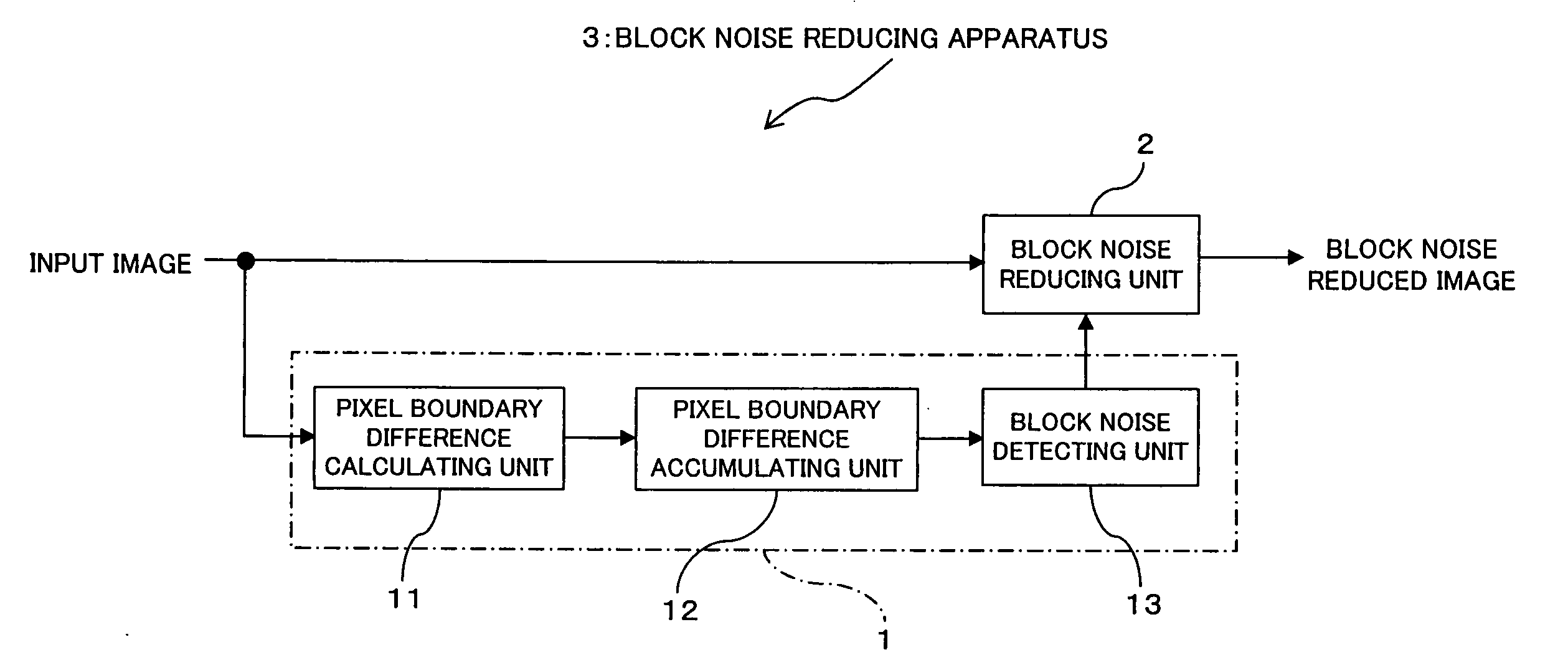
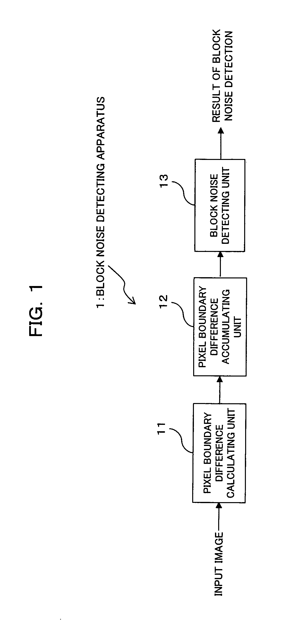
[0070]FIG. 1 is a block diagram showing a structure of a block noise detecting apparatus according to an embodiment of this invention. A block noise detecting apparatus 1 shown in FIG. 1 comprises a pixel boundary difference calculating unit 11, a pixel boundary difference accumulating unit 12, and a block noise detecting unit 13.

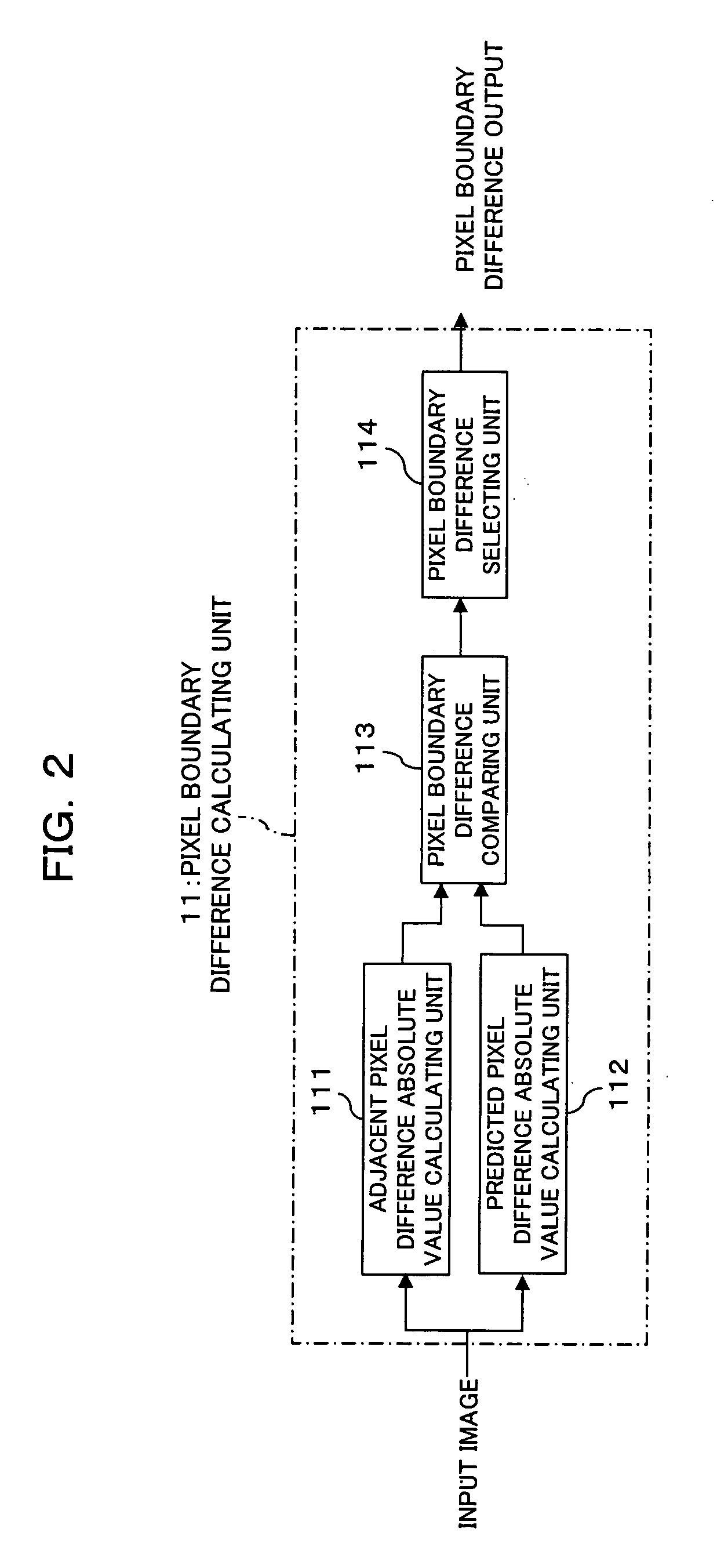
[0071]The pixel boundary difference calculating unit (pixel boundary difference detecting means) 11 calculates (detects) a difference (pixel boundary difference) between pixel values of adjacent pixels on a picture plane of input video signals. In this embodiment, as shown in FIGS. 3(A) and 3(B), the pixel boundary difference calculating unit 11 calculates a difference (absolute value) A between pixel values of adjacent pixels 5 and 6 across a certain pixel boundary P, calculates a difference (a...


PUM


Abstract

A pixel boundary difference detector detects a pixel boundary difference across a pixel boundary on the basis of a difference value between pixel values of adjacent pixels across the pixel boundary on a picture plane of an input image frame, and a predicted pixel value on the pixel boundary predicted from at least a plurality of pixels on one side of the pixel boundary, an accumulator accumulates the pixel boundary differences for one image frame, and a block noise detector detects a block noise on the basis of a result of the accumulation. The accuracy of block noise detection is improved, the effect of block noise reduction is improved, and the picture quality is improved.

Description

CROSS REFERENCE TO RELATED APPLICATIONS[0001]This application is based on and hereby claims priority to Japanese Application No. 2006-85334 filed on Mar. 27, 2006 in Japan, the contents of which are hereby incorporated by reference.BACKGROUND OF THE INVENTION[0002](1) Field of the Invention[0003]The present invention relates to a block noise detecting method and apparatus, and a block noise reducing method and apparatus. More specifically, the present invention relates to a method and apparatus for detecting a size, position and intensity of a block noise, and a method and apparatus for reducing the block noise on the basis of a result of the detection.[0004](2) Description of Related Art[0005]Beginning of spread of digital broadcasting, DVD players, disk recorders and so forth to which the digital image compression coding technique is applied gives us more opportunity to view compression-coded pictures. As this, compression-coded pictures are getting closer to us.[0006]MPEG-2, whic...

Claims


Application Information

Patent Timeline
Patent Type & Authority Applications(United States)
IPC IPC(8): G06K9/40G06K9/36H04N1/41H04N5/21H04N19/00H04N19/625H04N19/86
CPCH04N19/176H04N19/60H04N19/86H04N19/14H04N19/117
Inventor YAMADA, KOHJINAKAGATA, SHOHEI
Owner FUJITSU LTD
Why Eureka
Try Eureka